
Page 147 - Robots Androids and Animatrons : 12 Incredible Projects You Can Build
P. 147
RS232 computer connection. The command to send the information
out serially is
Serout Pin, Mode, Var
While we are not doing serial communication right now, it’s important
that you know you can.
Servo motors
Servo motors are geared direct current (DC) motors with a posi-
tional feedback control that allows the rotor of the motor to be accu-
rately positioned. The shaft of most hobbyist servo motors can be
positioned through a minimum of 90 degrees of rotation (±45
degrees). There are three wires to the servo motor. Two leads are
for power, typically 4.5V to 6V, and ground. The third wire feeds
the position control signal to the servo motor. The position con-
trol signal is a variable-width pulse. The pulse is varied between 1
and 2 milliseconds (ms). The width of the pulse controls the posi-
tion of the servo motor’s shaft.
Controlling servo motors with a PIC microcontroller is easy. The 1- to
2-ms control pulse signal must be sent to the motor 50 to 60 times
a second.
126
The pulsout command generates a pulse on the pin specified, for
the period specified [in 10-microsecond ( s) increments]. So the
command pulsout 1, 150 will place a 1.5 ms (10 s 150
1500 or 1.5 ms) pulse on pin 1. The 1.5-ms pulse will position the
servo motor’s shaft at midposition.
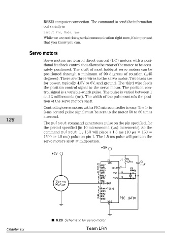
6.26 Schematic for servo motor
Team LRN
Chapter six