
Page 151 - Robots Androids and Animatrons : 12 Incredible Projects You Can Build
P. 151
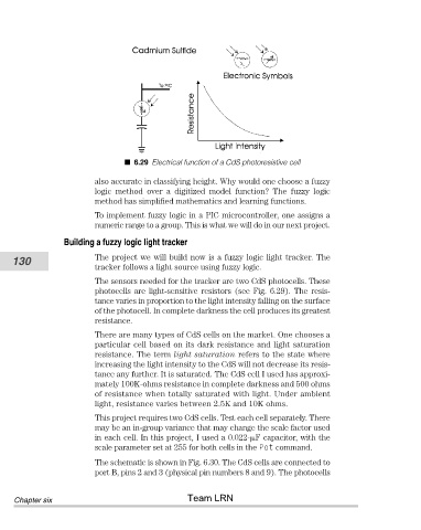
6.29 Electrical function of a CdS photoresistive cell

                                also accurate in classifying height. Why would one choose a fuzzy
                                logic  method  over  a  digitized  model  function?  The  fuzzy  logic
                                method has simplified mathematics and learning functions.
                                To implement fuzzy logic in a PIC microcontroller, one assigns a
                                numeric range to a group. This is what we will do in our next project.
                        Building a fuzzy logic light tracker

           130                  The project we will build now is a fuzzy logic light tracker. The
                                tracker follows a light source using fuzzy logic.
                                The sensors needed for the tracker are two CdS photocells. These
                                photocells  are  light-sensitive  resistors  (see  Fig.  6.29).  The  resis-
                                tance varies in proportion to the light intensity falling on the surface
                                of the photocell. In complete darkness the cell produces its greatest
                                resistance.
                                There are many types of CdS cells on the market. One chooses a
                                particular cell based on its dark resistance and light saturation
                                resistance. The term light saturation refers to the state where
                                increasing the light intensity to the CdS will not decrease its resis-
                                tance any further. It is saturated. The CdS cell I used has approxi-
                                mately 100K-ohms resistance in complete darkness and 500 ohms
                                of resistance when totally saturated with light. Under ambient
                                light, resistance varies between 2.5K and 10K ohms.
                                This project requires two CdS cells. Test each cell separately. There
                                may be an in-group variance that may change the scale factor used
                                in each cell. In this project, I used a 0.022- F capacitor, with the
                                scale parameter set at 255 for both cells in the Pot command.

                                The schematic is shown in Fig. 6.30. The CdS cells are connected to
                                port B, pins 2 and 3 (physical pin numbers 8 and 9). The photocells


                                                       Team LRN
            Chapter six