
Page 154 - Robots Androids and Animatrons : 12 Incredible Projects You Can Build
P. 154
133
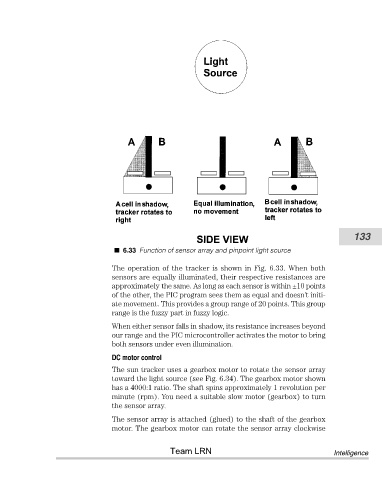
6.33 Function of sensor array and pinpoint light source
The operation of the tracker is shown in Fig. 6.33. When both
sensors are equally illuminated, their respective resistances are
approximately the same. As long as each sensor is within ±10 points
of the other, the PIC program sees them as equal and doesn’t initi-
ate movement. This provides a group range of 20 points. This group
range is the fuzzy part in fuzzy logic.
When either sensor falls in shadow, its resistance increases beyond
our range and the PIC microcontroller activates the motor to bring
both sensors under even illumination.
DC motor control
The sun tracker uses a gearbox motor to rotate the sensor array
toward the light source (see Fig. 6.34). The gearbox motor shown
has a 4000:1 ratio. The shaft spins approximately 1 revolution per
minute (rpm). You need a suitable slow motor (gearbox) to turn
the sensor array.
The sensor array is attached (glued) to the shaft of the gearbox
motor. The gearbox motor can rotate the sensor array clockwise
Team LRN Intelligence