
Page 155 - Robots Androids and Animatrons : 12 Incredible Projects You Can Build
P. 155
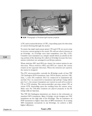
6.34 Photograph of finished light tracker projects


                                (CW) and counterclockwise (CCW), depending upon the direction
                                of current flowing through the motor.

                                To rotate the shaft (and sensor array) CW and CCW, we need a way
                                to reverse current going to the motor. We will use what is known as
                                an  H-bridge.  An  H-bridge  uses  four  transistors  (see  Fig.  6.35).
                                Consider each transistor as a simple on/off switch as shown in the
           134                  top portion of the drawing. It’s called an H-bridge because the tran-
                                sistors (switches) are arranged in an H-type pattern.

                                When switches SW1 and SW4 are closed, the motor rotates in one
                                direction. When switches SW2 and SW3 are closed, the motor
                                rotates in the opposite direction. When the switches are opened,
                                the motor is stopped.

                                The PIC microcontroller controls the H-bridge made of four TIP
                                120 Darlington NPN transistors; four 1N514 diodes; and two 10K-
                                     1
                                ohm,   -watt (W) resistors. Pin 0 is connected to transistors Q1
                                      4
                                and Q4. Pin 1 is connected to transistors Q3 and Q4. Using either
                                pin 0 or 1, the proper transistors are turned on and off to achieve
                                CW or CCW rotation. The microcontroller can stop, rotate CW, or
                                rotate CCW, depending upon the reading from the sensor array.
                                Make sure the 10K-ohm resistors are placed properly or the H-
                                bridge will not function.

                                The TIP 120 Darlington transistors are drawn in the schematic as
                                standard NPN transistors. Many H-bridge circuit designs use PNP
                                transistors on the high side of the H-bridge. The on resistance of
                                PNP transistors is higher than that of NPN transistors. So in using
                                NPN  transistors  exclusively  in  our  H-bridge,  we  achieve  a  little
                                higher efficiency.
                                                       Team LRN
            Chapter six