
Page 225 - Robots Androids and Animatrons : 12 Incredible Projects You Can Build
P. 225
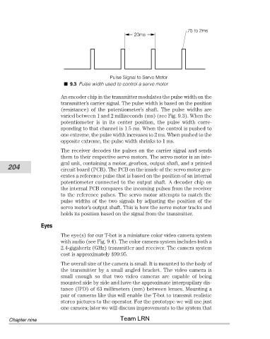
20ms


                                                   Pulse Signal to Servo Motor   .75 to 2ms
                                   9.3 Pulse width used to control a servo motor

                                An encoder chip in the transmitter modulates the pulse width on the
                                transmitter’s carrier signal. The pulse width is based on the position
                                (resistance)  of  the  potentiometer’s  shaft.  The  pulse  widths  are
                                varied between 1 and 2 milliseconds (ms) (see Fig. 9.3). When the
                                potentiometer  is  in  its  center  position,  the  pulse  width  corre-
                                sponding to that channel is 1.5 ms. When the control is pushed to
                                one extreme, the pulse width increases to 2 ms. When pushed to the
                                opposite extreme, the pulse width shrinks to 1 ms.
                                The receiver decodes the pulses on the carrier signal and sends
                                them to their respective servo motors. The servo motor is an inte-
                                gral unit, containing a motor, gearbox, output shaft, and a printed
           204                  circuit board (PCB). The PCB on the inside of the servo motor gen-

                                erates a reference pulse that is based on the position of an internal
                                potentiometer connected to the output shaft. A decoder chip on
                                the internal PCB compares the incoming pulses from the receiver
                                to the reference pulses. The servo motor attempts to match the
                                pulse  widths  of  the  two  signals  by  adjusting  the  position  of  the
                                servo motor’s output shaft. This is how the servo motor tracks and
                                holds its position based on the signal from the transmitter.

                        Eyes
                                The eye(s) for our T-bot is a miniature color video camera system
                                with audio (see Fig. 9.4). The color camera system includes both a
                                2.4-gigahertz (GHz) transmitter and receiver. The camera system
                                cost is approximately $99.95.
                                The overall size of the camera is small. It is mounted to the body of
                                the transmitter by a small angled bracket. The video camera is
                                small  enough  so  that  two  video  cameras  are  capable  of  being
                                mounted side by side and have the approximate interpupilary dis-
                                tance (IPD) of 63 millimeters (mm) between lenses. Mounting a
                                pair of cameras like this will enable the T-bot to transmit realistic
                                stereo pictures to the operator. For the prototype we will use just
                                one camera; later we will discuss improvements to the system that
                                                       Team LRN
            Chapter nine