
Page 276 - Robots Androids and Animatrons : 12 Incredible Projects You Can Build
P. 276
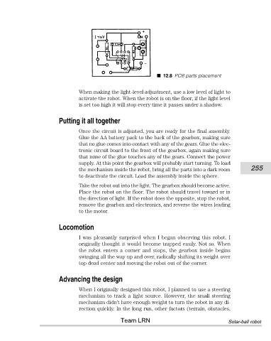
12.8 PCB parts placement


                                       When making the light-level adjustment, use a low level of light to
                                       activate the robot. When the robot is on the floor, if the light level
                                       is set too high it will stop every time it passes under a shadow.


                               Putting it all together
                                       Once the circuit is adjusted, you are ready for the final assembly.
                                       Glue the AA battery pack to the back of the gearbox, making sure
                                       that no glue comes into contact with any of the gears. Glue the elec-
                                       tronic circuit board to the front of the gearbox, again making sure
                                       that none of the glue touches any of the gears. Connect the power
                                       supply. At this point the gearbox will probably start turning. To load
                                       the mechanism inside the robot, bring all the parts into a dark room  255
                                       to deactivate the circuit. Load the assembly inside the sphere.

                                       Take the robot out into the light. The gearbox should become active.
                                       Place the robot on the floor. The robot should travel toward or in
                                       the direction of light. If the robot does the opposite, stop the robot,
                                       remove the gearbox and electronics, and reverse the wires leading
                                       to the motor.


                               Locomotion
                                       I was pleasantly surprised when I began observing this robot. I
                                       originally thought it would become trapped easily. Not so. When
                                       the  robot  enters  a  corner  and  stops,  the  gearbox  inside  begins
                                       swinging all the way up and over, radically shifting its weight over
                                       top dead center and moving the robot out of the corner.


                               Advancing the design

                                       When I originally designed this robot, I planned to use a steering
                                       mechanism to track a light source. However, the small steering
                                       mechanism didn’t have enough weight to turn the robot in any di-
                                       rection quickly. In the long run, other factors (terrain, obstacles,
                                                       Team LRN                                   Solar-ball robot