
Page 168 - Rock Mechanics For Underground Mining
P. 168
PRE-MINING STATE OF STRESS
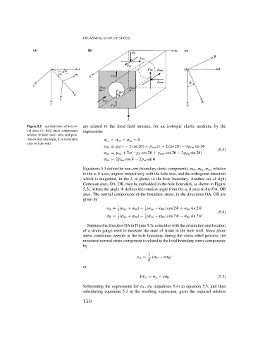
Figure 5.5 (a) Definition of hole lo- are related to the local field stresses, for an isotropic elastic medium, by the
cal axes; (b) field stress components expressions
relative to hole local axes and posi-
tion co-ordinate angle,
; (c) reference rr = r
= rn = 0
axes on hole wall.
= p ll (1 − 2 cos 2
) + p mm (1 + 2 cos 2
) − 4p lm sin 2
(5.3)
nn = p nn + 2 (−p ll cos 2
+ p mm cos 2
− 2p lm sin 2
)
n = 2p mn cos
− 2p nl sin
Equations 5.3 define the non-zero boundary stress components,
,
n , nn , relative
to the n,
axes, aligned respectively with the hole axis, and the orthogonal direction
which is tangential, in the l, m plane, to the hole boundary. Another set of right
Cartesian axes, OA, OB, may be embedded in the hole boundary, as shown in Figure
5.5c, where the angle defines the rotation angle from the n,
axes to the OA, OB
axes. The normal components of the boundary stress, in the directions OA, OB are
given by
1 1
A = ( nn +
) + ( nn −
) cos 2 +
n sin 2
2 2
(5.4)
1
1
B = ( nn +
) − ( nn −
) cos 2 −
n sin 2
2 2
Suppose the direction OA in Figure 5.5c coincides with the orientation and location
of a strain gauge used to measure the state of strain in the hole wall. Since plane
stress conditions operate at the hole boundary during the stress relief process, the
measured normal strain component is related to the local boundary stress components
by
1
ε A = ( A − B )
E
or
(5.5)
Eε A = A − B
Substituting the expressions for A , B (equations 5.4) in equation 5.5, and then
substituting equations 5.3 in the resulting expression, gives the required relation
150