Page 167 - Rock Mechanics For Underground Mining
P. 167

METHODS OF IN SITU STRESS DETERMINATION

              (a)                       by dip,  , and dip direction,  , relative to a set of global axes x, y, z. Relative
                                        to these axes, the ambient field stress components (prior to drilling the hole) are
                                        p xx , p yy , P zz , p xy , p yz , p zx . A convenient set of local axes, l, m, n, for the borehole
                                        is also shown in Figure 5.5a, with the n axis directed parallel to the hole axis, and
                                        the m axis lying in the horizontal (x, y) plane. The field stress components expressed
                                        relative to the hole local axes, i.e. p ll , p ln , etc., are readily related to the global
                                        components p xx , p xz , etc., through the stress transformation equation and a rotation
                                        matrix defined by
                                                  ⎡             ⎤   ⎡                                ⎤
                                                                      − sin   cos    sin    cos   cos
                                                      xl    xm    xn
                                                                    ⎣ − sin   sin    − cos
                                             [R] =  ⎣   yl    ym    yn  ⎦  =                cos   sin   ⎦
                                                                        cos          0      sin
                                                      zl    zm    zn
                                          In Figure 5.5b, the location of a point on the wall of the borehole is defined by
                                        the angle 
 measured clockwise in the l, m plane. Boundary stresses at the point

                                                               (b)


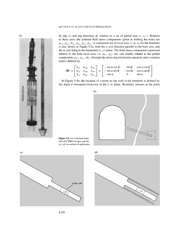
                                        Figure 5.4 (a) A triaxial strain
                                        cell (of CSIRO design), and (b),
                                        (c), (d) its method of application.


              (c)                                               (d)


                                        149
   162   163   164   165   166   167   168   169   170   171   172