
Page 181 - Rock Mechanics For Underground Mining
P. 181
PROBLEMS
−3
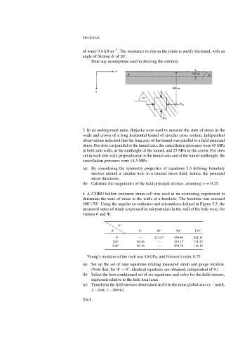
of water 9.8kNm . The resistance to slip on the joints is purely frictional, with an
◦
angle of friction of 20 .
State any assumptions used in deriving the solution.
3 In an underground mine, flatjacks were used to measure the state of stress in the
walls and crown of a long horizontal tunnel of circular cross section. Independent
observations indicated that the long axis of the tunnel was parallel to a field principal
stress. For slots cut parallel to the tunnel axis, the cancellation pressures were 45 MPa
in both side walls, at the midheight of the tunnel, and 25 MPa in the crown. For slots
cut in each side wall, perpendicular to the tunnel axis and at the tunnel midheight, the
cancellation pressures were 14.5 MPa.
(a) By considering the symmetry properties of equations 5.3 defining boundary
stresses around a circular hole in a triaxial stress field, deduce the principal
stress directions.
(b) Calculate the magnitudes of the field principal stresses, assuming = 0.25.
4 A CSIRO hollow inclusion strain cell was used in an overcoring experiment to
determine the state of strain in the walls of a borehole. The borehole was oriented
◦
◦
300 /70 . Using the angular co-ordinates and orientations defined in Figure 5.5, the
measured states of strain (expressed in microstrains) in the wall of the hole were, for
various
and :
◦
◦ 0 ◦ 45 ◦ 90 ◦ 135 ◦
0 ◦ — 213.67 934.41 821.11
120 ◦ 96.36 — 349.15 131.45
240 ◦ 96.36 — 560.76 116.15
Young’s modulus of the rock was 40 GPa, and Poisson’s ratio, 0.25.
(a) Set up the set of nine equations relating measured strain and gauge location.
◦
(Note that, for = 0 , identical equations are obtained, independent of
.)
(b) Select the best conditioned set of six equations, and solve for the field stresses,
expressed relative to the hole local axes.
(c) Transform the field stresses determined in (b) to the mine global axes (x – north,
y – east, z – down).
163