
Page 20 - Rock Mechanics For Underground Mining
P. 20
ROCK MECHANICS AND MINING ENGINEERING
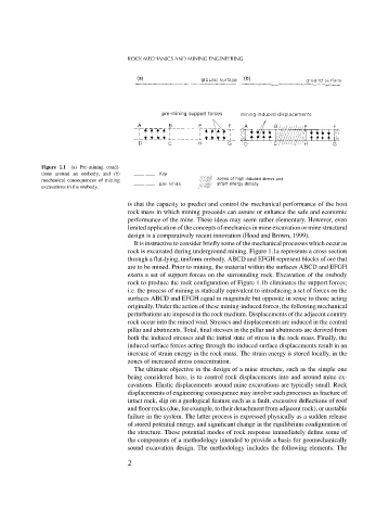
Figure 1.1 (a) Pre-mining condi-
tions around an orebody, and (b)
mechanical consequences of mining
excavations in the orebody.
is that the capacity to predict and control the mechanical performance of the host
rock mass in which mining proceeds can assure or enhance the safe and economic
performance of the mine. These ideas may seem rather elementary. However, even
limited application of the concepts of mechanics in mine excavation or mine structural
design is a comparatively recent innovation (Hood and Brown, 1999).
It is instructive to consider briefly some of the mechanical processes which occur as
rock is excavated during underground mining. Figure 1.1a represents a cross section
through a flat-lying, uniform orebody. ABCD and EFGH represent blocks of ore that
are to be mined. Prior to mining, the material within the surfaces ABCD and EFGH
exerts a set of support forces on the surrounding rock. Excavation of the orebody
rock to produce the rock configuration of Figure 1.1b eliminates the support forces;
i.e. the process of mining is statically equivalent to introducing a set of forces on the
surfaces ABCD and EFGH equal in magnitude but opposite in sense to those acting
originally. Under the action of these mining-induced forces, the following mechanical
perturbations are imposed in the rock medium. Displacements of the adjacent country
rock occur into the mined void. Stresses and displacements are induced in the central
pillar and abutments. Total, final stresses in the pillar and abutments are derived from
both the induced stresses and the initial state of stress in the rock mass. Finally, the
induced surface forces acting through the induced surface displacements result in an
increase of strain energy in the rock mass. The strain energy is stored locally, in the
zones of increased stress concentration.
The ultimate objective in the design of a mine structure, such as the simple one
being considered here, is to control rock displacements into and around mine ex-
cavations. Elastic displacements around mine excavations are typically small. Rock
displacements of engineering consequence may involve such processes as fracture of
intact rock, slip on a geological feature such as a fault, excessive deflections of roof
and floor rocks (due, for example, to their detachment from adjacent rock), or unstable
failure in the system. The latter process is expressed physically as a sudden release
of stored potential energy, and significant change in the equilibrium configuration of
the structure. These potential modes of rock response immediately define some of
the components of a methodology intended to provide a basis for geomechanically
sound excavation design. The methodology includes the following elements. The
2