
Page 315 - Rock Mechanics For Underground Mining
P. 315
INSTABILITY DUE TO PILLAR CRUSHING
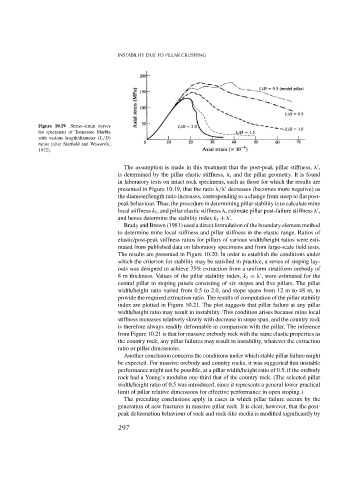
Figure 10.19 Stress–strain curves
for specimens of Tennessee Marble
with various length/diameter (L/D)
ratios (after Starfield and Wawersik,
1972).
The assumption is made in this treatment that the post-peak pillar stiffness, ,
is determined by the pillar elastic stiffness, , and the pillar geometry. It is found
in laboratory tests on intact rock specimens, such as those for which the results are
presented in Figure 10.19, that the ratio / decreases (becomes more negative) as
the diameter/length ratio increases, corresponding to a change from steep to flat post-
peak behaviour. Thus, the procedure in determining pillar stability is to calculate mine
local stiffness k , and pillar elastic stiffness , estimate pillar post-failure stiffness ,
and hence determine the stability index k + .
Brady and Brown (1981) used a direct formulation of the boundary element method
to determine mine local stiffness and pillar stiffness in the elastic range. Ratios of
elastic/post-peak stiffness ratios for pillars of various width/height ratios were esti-
mated from published data on laboratory specimens and from large-scale field tests.
The results are presented in Figure 10.20. In order to establish the conditions under
which the criterion for stability may be satisfied in practice, a series of stoping lay-
outs was designed to achieve 75% extraction from a uniform stratiform orebody of
8 m thickness. Values of the pillar stability index, k = , were estimated for the
central pillar in stoping panels consisting of six stopes and five pillars. The pillar
width/height ratio varied from 0.5 to 2.0, and stope spans from 12 m to 48 m, to
provide the required extraction ratio. The results of computation of the pillar stability
index are plotted in Figure 10.21. The plot suggests that pillar failure at any pillar
width/height ratio may result in instability. This condition arises because mine local
stiffness increases relatively slowly with decrease in stope span, and the country rock
is therefore always readily deformable in comparison with the pillar. The inference
from Figure 10.21 is that for massive orebody rock with the same elastic properties as
the country rock, any pillar failures may result in instability, whatever the extraction
ratio or pillar dimensions.
Another conclusion concerns the conditions under which stable pillar failure might
be expected. For massive orebody and country rocks, it was suggested that unstable
performance might not be possible, at a pillar width/height ratio of 0.5, if the orebody
rock had a Young’s modulus one-third that of the country rock. (The selected pillar
width/height ratio of 0.5 was introduced, since it represents a general lower practical
limit of pillar relative dimensions for effective performance in open stoping.)
The preceding conclusions apply in cases in which pillar failure occurs by the
generation of new fractures in massive pillar rock. It is clear, however, that the post-
peak deformation behaviour of rock and rock-like media is modified significantly by
297