
Page 333 - Rock Mechanics For Underground Mining
P. 333
SUPPORT AND REINFORCEMENT PRINCIPLES
be defined as 2.25 radii, at which distance from the face, the radial displacement is
within approximately 5% of the comparable plane strain value.
The graph in Figure 11.1 shows a plot of the radial support pressure, p i , required
at a point to limit the radial boundary displacement, i , to the value given by the
abscissa. If the restraint provided by the face at step 2 were not available, internal
support pressures given by the ordinates of points B and C would be required to limit
the displacements to their actual values. Different curves are shown for the side walls
and for the roof. Extra support pressure is required to limit the displacement of the
roof to a particular value because of the extra load imposed by the action of gravity
on loosened rock in the roof.
By step 3, the heading has been mucked out and steel sets have been installed
close to the face. At this stage, the sets carry no load because no deformation of
the rock has occurred since their installation. This assumes that the rock mass does
not exhibit time-dependent stress–strain behaviour. On the graph in Figure 11.1, the
radial displacements of points in the roof and in the side wall, are still those given by
points B and C.
In step 4, the heading is advanced about one and a half tunnel diameters beyond
X–X by a further cycle of drilling and blasting. The restraint offered by the proximity
of the face is now negligible, and there is further radial displacement of the rock
surface at X–X as indicated by the curves CEG and BFH in Figure 11.1. This induces
load in the steel sets which are assumed to show linear radial stress–displacement
behaviour. Thus the supports typically load along a path such as DEF, known as the
support reaction or available support line. The curve representing the behaviour
of the rock mass is known as the ground characteristic or required support line.
Equilibrium between the rock and the steel sets is reached at point E for the side wall
and point F for the roof. It is important to note that most of the redistributed stress
arising from creation of the excavation is carried by the rock and not by the steel
sets.
If steel sets had not been installed after the last two stages of heading advance,
the radial displacements at X–X would have increased along the dashed curves EG
and FH. In the case of the side walls, equilibrium would have been reached at point
G. However, the support pressure required to limit displacement of the roof may
drop to a minimum and then increase again as rock becomes loosened and has to
be held up. In this illustrative example, the roof would collapse if no support were
provided.
The rational design of support and reinforcement systems must take into account
the interaction between the support or reinforcing elements and the rock mass, de-
scribed qualitatively for this simple example. It is clear from this analysis that control
of rock displacements is the major rˆole of support and reinforcement systems. As
Figure 11.1 shows, enough displacement must be allowed to enable the rock mass
strength to be mobilised sufficiently to restrict required support loads to practicable
levels. However, excessive displacement, which would lead to a loosening of the
rock mass and a reduction in its load-carrying capacity, must not be permitted to
occur.
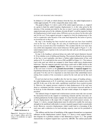
The stiffness and the time of installation of the support element have an important
Figure 11.3 Illustration of the influ-
influence on this displacement control. Figure 11.3 shows a rock–support interac-
ence of support stiffness and of the
timing of its installation on support tion diagram for a problem similar to that illustrated in Figure 11.1. The ground
performance. characteristic or required support line is given by ABCDE. The earliest practicable
315