
Page 338 - Rock Mechanics For Underground Mining
P. 338
ROCK SUPPORT AND REINFORCEMENT
Table 11.1 Required support line calculations for sample problem.
p i (MPa) 10 4 2 1.222 1.0 0.5 0.2 0.1
r e (m) — — — — 3.316 4.690 7.415 10.487
i (m) 0 0.015 0.020 0.022 0.027 0.063 0.228 0.632
(r e − a)(MPa) 0 0 0 0 0.008 0.042 0.110 0.187
p roof = p i + (r e − a)(MPa) 10 4 2 1.222 1.008 0.542 0.310 0.287
p floor = p i − (r e − a)(MPa) 10 4 2 1.222 0.992 0.458 0.090 (−0.087)
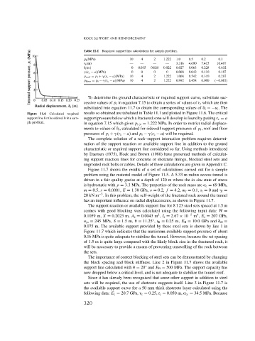
To determine the ground characteristic or required support curve, substitute suc-
cessive values of p i in equation 7.15 to obtain a series of values of r e which are then
substituted into equation 11.7 to obtain the corresponding values of i =−u i . The
Figure 11.6 Calculated required results so obtained are tabulated in Table 11.1 and plotted in Figure 11.6. The critical
support line for the sidewalls in a sam- support pressure below which a fractured zone will develop is found by putting r e = a
ple problem. in equation 7.15 which gives p icr = 1.222 MPa. In order to restrict radial displace-
ments to values of i , calculated for sidewall support pressures of p i , roof and floor
pressures of p i + (r e − a) and p i − (r e − a) will be required.
The complete solution of a rock–support interaction problem requires determi-
nation of the support reaction or available support line in addition to the ground
characteristic or required support line considered so far. Using methods introduced
by Daemen (1975), Hoek and Brown (1980) have presented methods of calculat-
ing support reaction lines for concrete or shotcrete linings, blocked steel sets and
ungrouted rock bolts or cables. Details of these calculations are given in Appendix C.
Figure 11.7 shows the results of a set of calculations carried out for a sample
problem using the material model of Figure 11.5. A 5.33 m radius access tunnel is
driven in a fair quality gneiss at a depth of 120 m where the in situ state of stress
is hydrostatic with p = 3.3 MPa. The properties of the rock mass are c = 69 MPa,
m = 0.5, s = 0.0001, E = 1.38 GPa, = 0.2, f = 4.2, m r = 0.1, s r = 0 and r =
−3
20 kN m . In this problem, the self-weight of the fractured rock around the tunnel
has an important influence on radial displacements, as shown in Figure 11.7.
The support reaction or available support line for8I23 steel sets spaced at 1.5 m
centres with good blocking was calculated using the following input data: W =
4
2
0.1059 m, X = 0.2023 m, A s = 0.0043 m , I s = 2.67 × 10 −5 m , E s = 207 GPa,
◦
ys = 245 MPa, S = 1.5m,
= 11.25 , t B = 0.25 m, E B = 10.0 GPa and i0 =
0.075 m. The available support provided by these steel sets is shown by line 1 in
Figure 11.7 which indicates that the maximum available support pressure of about
0.16 MPa is quite adequate to stabilise the tunnel. However, because the set spacing
of 1.5 m is quite large compared with the likely block size in the fractured rock, it
will be necessary to provide a means of preventing unravelling of the rock between
the sets.
The importance of correct blocking of steel sets can be demonstrated by changing
the block spacing and block stiffness. Line 2 in Figure 11.7 shows the available
◦
support line calculated with
= 20 and E B = 500 MPa. The support capacity has
now dropped below a critical level, and is not adequate to stabilise the tunnel roof.
Since it has already been recognised that some other support in addition to steel
sets will be required, the use of shotcrete suggests itself. Line 3 in Figure 11.7 is
the available support curve for a 50 mm thick shotcrete layer calculated using the
following data: E c = 20.7GPa, c = 0.25, t c = 0.050 m, cc = 34.5 MPa. Because
320