
Page 339 - Rock Mechanics For Underground Mining
P. 339
ROCK–SUPPORT INTERACTION ANALYSIS
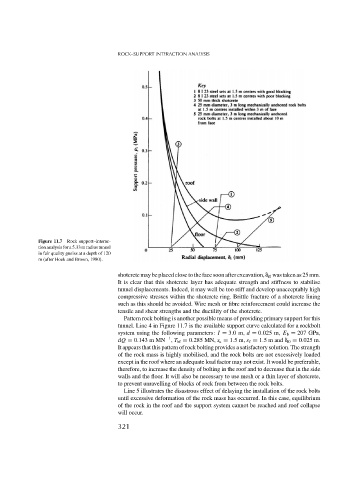
Figure 11.7 Rock support–interac-
tion analysis for a 5.33 m radius tunnel
in fair quality gneiss at a depth of 120
m (after Hoek and Brown, 1980).
shotcretemaybe placed close tothe facesoon after excavation, i0 was takenas 25 mm.
It is clear that this shotcrete layer has adequate strength and stiffness to stabilise
tunnel displacements. Indeed, it may well be too stiff and develop unacceptably high
compressive stresses within the shotcrete ring. Brittle fracture of a shotcrete lining
such as this should be avoided. Wire mesh or fibre reinforcement could increase the
tensile and shear strengths and the ductility of the shotcrete.
Pattern rock bolting is another possible means of providing primary support for this
tunnel. Line 4 in Figure 11.7 is the available support curve calculated for a rockbolt
system using the following parameters: I = 3.0m, d = 0.025 m, E b = 207 GPa,
−1
dQ = 0.143 m MN , T bf = 0.285 MN, s c = 1.5m, s = 1.5 m and i0 = 0.025 m.
It appears that this pattern of rock bolting provides a satisfactory solution. The strength
of the rock mass is highly mobilised, and the rock bolts are not excessively loaded
except in the roof where an adequate load factor may not exist. It would be preferable,
therefore, to increase the density of bolting in the roof and to decrease that in the side
walls and the floor. It will also be necessary to use mesh or a thin layer of shotcrete,
to prevent unravelling of blocks of rock from between the rock bolts.
Line 5 illustrates the disastrous effect of delaying the installation of the rock bolts
until excessive deformation of the rock mass has occurred. In this case, equilibrium
of the rock in the roof and the support system cannot be reached and roof collapse
will occur.
321