
Page 36 - Rock Mechanics For Underground Mining
P. 36
STRESS AND INFINITESIMAL STRAIN
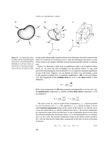
Figure 2.1 (a) A finite body subject acting on the orthogonally oriented surfaces of an elementary free body centred on the
to surface loading; (b) determination point. If a Cartesian set of reference axes is used, the elementary free body is a cube
of the forces, and related quantities, whose surfaces are oriented with their outward normals parallel with the co-ordinate
operating on an internal surface; (c)
axes.
specification of the state of stress at a
point in terms of the traction compo- Figure 2.1a illustrates a finite body in equilibrium under a set of applied surface
nents on the face of a cubic free body. forces, P j . To assess the state of loading over any interior surface, S i , one could
proceed by determining the load distribution over S i required to maintain equilibrium
of part of the body. Suppose, over an element of surface A surrounding a point
O, the required resultant force to maintain equilibrium is R, as shown in Figure
2.1b. The magnitude of the resultant stress r at O, or the stress vector, is then
defined by
R
r = lim
A→0 A
If the vector components of R acting normally and tangentially to A are N, S,
the normal stress component, n , and the resultant shear stress component, ,atO
are defined by
N S
n = lim , = lim
A→0 A A→0 A
The stress vector, r , may be resolved into components t x , t y , t z directed parallel
to a set of reference axes x, y, z. The quantities t x , t y , t z , shown in Figure 2.1b are
called traction components acting on the surface at the point O. As with the stress
vector, the normal stress, n , and the resultant shear stress, , the traction components
are expressed in units of force per unit area. A case of particular interest occurs when
the outward normal to the elementary surface A is oriented parallel to a co-ordinate
axis, e.g. the x axis. The traction components acting on the surface whose normal is
the x axis are then used to define three components of the state of stress at the point
of interest,
xx = t x , xy = t y , xz = t z (2.1)
18