
Page 389 - Rock Mechanics For Underground Mining
P. 389
COMPONENTS OF A SUPPORTED MINE STRUCTURE
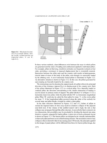
Figure 13.2 Pillar layout for extrac-
tion of an inclined orebody, show-
ing biaxially confined transverse and
longitudinal pillars, ‘A’ and ‘B’,
respectively.
In these various methods, clear differences exist between the ways in which pillars
are generated and the states of loading and confinement applied to individual pillars.
For example, pillars in flat-lying, stratiform orebodies are frequently isolated on four
sides, providing a resistance to imposed displacement that is essentially uniaxial.
Interaction between the pillar ends and the country rock results in heterogeneous,
triaxial states of stress in the body of the pillar, even though it is uniaxially loaded
by the abutting rock. A set of uniaxially loaded pillars is illustrated in Figure 12.2.
An alternative situation is shown in Figure 13.2. In this case, the pillars generated by
open stoping are biaxially loaded by the country rock.
The terminology used in denoting the support mode of a pillar reflects the principal
direction of the resistance imposed by it to displacement of the country rock. Each
of the pillars illustrated in Figure 12.2 is a vertical pillar. For a biaxially loaded or
confined pillar, the direction corresponding to the smaller dimension of loading is
used to denote its primary mode of support. The pillar labelled ‘A’ in Figure 13.2 is a
horizontal, transverse pillar, while the pillar labelled ‘B’ is a horizontal, longitudinal
pillar. Pillar ‘B’ could also be called the floor pillar for stope ‘1’, or the crown pillar
for stope ‘2’. If the longitudinal pillar persisted along the strike of the orebody for
several stope and pillar blocks, it might be called a chain pillar.
In the mine structures illustrated in Figures 12.2 and 13.2, failure of pillars to
sustain the imposed states of stress may result in extensive collapse of the adjacent
near-field rock. If the volume of the unfilled mined void is high, the risk is that
collapse may propagate through the pillar structure. In an orebody that is extensive in
two dimensions, this possibility may be precluded by dividing the deposit into mine
districts, or panels, separated by barrier pillars. A plan view of such a schematic layout
is shown in Figure 13.3. The barrier pillars are designed to be virtually indestructible,
so that each panel performs as an isolated mining domain. The maximum extent of any
collapse is then restricted to that of any mining panel. Obviously, the principles applied
in the design of panel pillars will be different from those for barrier pillar design, due
371