
Page 422 - Rock Mechanics For Underground Mining
P. 422
PILLAR SUPPORTED MINING METHODS
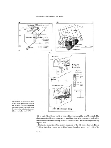
Figure 13.31 (a) Plane strain analy-
sis of G2 stope cross section; (b) prob-
lem geometry for three-dimensional
analysis; (c) contours of dip slip on the
Betafaultbeforeandafterextensionof
G2 stope (after Lee et al., 1990).
100 m high. Rib pillars were 32 m long, while the crown pillar was 32 m thick. The
dimensions of stable stope spans were established from prior experience, while pillar
dimensions were determined by analysis intended to limit pillar crushing or spalling
at pillar lines.
During the extraction of the eastern extension of the G2 stope, shown in Figure
13.31b, a fault slip rockburst resulted in substantial spalling from the underside of the
404