
Page 460 - Rock Mechanics For Underground Mining
P. 460
LONGWALL AND CAVING MINING METHODS
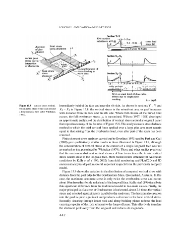
Figure 15.8 Vertical stress redistri- immediately behind the face and near the rib side. As shown in sectionsY–Yand
bution in the plane of the seam around X 2 – X 2 in Figure 15.8, the vertical stress in the mined-out area or goaf increases
a longwall coal face (after Whittaker,
with distance from the face and the rib side. Where full closure of the mined void
1974).
occurs, the full overburden stress, p, is transmitted. Wilson (1977, 1981) developed
an approximate analysis of the distribution of vertical stress around a longwall panel
that reproduces many of the features of Figure 15.8. This analysis uses a stress balance
method in which the total vertical force applied over a large plan area must remain
equal to that arising from the overburden load, even after part of the seam has been
removed.
Finite element stress analyses carried out by Everling (1973) and by Park and Gall
(1989) gave qualitatively similar results to those illustrated in Figure 15.8, although
the concentration of vertical stress at the corners of a single longwall face was not
as marked as that postulated by Whittaker (1974). These and other studies predicted
that the maximum abutment vertical stresses of four to six times the in situ vertical
stress occurs close to the longwall face. More recent results obtained for Australian
conditions by Kelly et al. (1996, 2002) from field monitoring and FLAC2D and 3D
numerical analyses depart in several important respects from the previously accepted
model.
Figure 15.9 shows the variation in the distribution of computed vertical stress with
distance from the goaf edge for the Gordonstone Mine, Queensland, Australia. In this
case, the maximum abutment stress is only twice the overburden stress and occurs
about 10 m from the rib side and ahead of the longwall face. Kellyet al. (1996) attribute
this significant difference from the traditional model to two main causes. Firstly, the
major principal in situ stress at Gordonstone is horizontal, about 2.4 times the vertical
stress and oriented approximately parallel to the roadways. The horizontal relaxation
into the goaf is quite significant and produces a decrease in the local vertical stress.
Secondly, shearing through intact rock and along bedding planes reduces the load
carrying capacity of the rock adjacent to the longwall zone. This effectively transfers
the abutment peak away from the longwall and reduces its magnitude.
442