
Page 465 - Rock Mechanics For Underground Mining
P. 465
LONGWALL COAL MINING
15.3.4 Face support
Activesupportofthenewlyexposedroofstrataimmediatelybehindthefaceisrequired
to prevent the uncontrolled collapse of the roof rock and to promote effective caving
of the waste. Support systems used for this purpose consist of a series of chocks each
containing four or six yielding, hydraulic legs. The upper part of each chock is formed
by roof beams or a canopy. Where the waste is friable or breaks into small pieces,
or where significant horizontal components of waste displacement towards the face
occur, shield supports are used. These supports include not only a roof canopy, but
also a heavy rear shield connected to the base by linkages.
The essential geomechanics concern in the design and operation of face support
systems, is the value of the support thrust to be provided against the roof, and the
associated question of the yield loads of the hydraulic legs. An inadequate setting or
yield load may permit excessive convergence to occur at the face, and may permit
uneven caving to develop. For example, strong sandstone roofs require high shear
forces at the cave line to promote caving. Conversely, excessive setting loads may
damage weak roof or floor rocks.
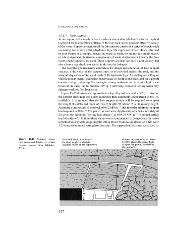
Figure 15.15 illustrates an approach developed by Ashwin et al. (1970) to estimate
the support thrust required under conditions then commonly encountered in the UK
coalfields. It is assumed that the face support system will be required to support
the weight of a detached block of rock of height 2H where H is the mining height.
−3
Assuming a unit weight of roof rock of 0.02 MN m , this gives the minimum support
2
load required as 0.04 H MN per m of roof area. Application of a factor of safety of
−2
2.0 gives the minimum ‘setting load density’ as 0.08 H MN m . Nominal setting
load densities of 1.33 times these values were recommended to compensate for losses
in the hydraulic system supplying the setting thrust. Nominal yield load densities were
1.25 times the nominal setting load densities. The support load densities calculated by
Figure 15.15 Assumed caving
mechanism and loading on a face
powered support (after Whittaker,
1974).
447