
Page 467 - Rock Mechanics For Underground Mining
P. 467
LONGWALL COAL MINING
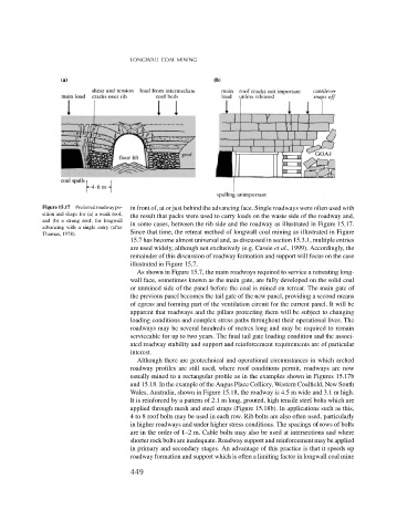
Figure 15.17 Preferred roadway po- in front of, at or just behind the advancing face. Single roadways were often used with
sition and shape for (a) a weak roof, the result that packs were used to carry loads on the waste side of the roadway and,
and (b) a strong roof, for longwall
advancing with a single entry (after in some cases, between the rib side and the roadway as illustrated in Figure 15.17.
Since that time, the retreat method of longwall coal mining as illustrated in Figure
Thomas, 1978).
15.7 has become almost universal and, as discussed in section 15.3.1, multiple entries
are used widely, although not exclusively (e.g. Cassie et al., 1999). Accordingly, the
remainder of this discussion of roadway formation and support will focus on the case
illustrated in Figure 15.7.
As shown in Figure 15.7, the main roadways required to service a retreating long-
wall face, sometimes known as the main gate, are fully developed on the solid coal
or unmined side of the panel before the coal is mined on retreat. The main gate of
the previous panel becomes the tail gate of the new panel, providing a second means
of egress and forming part of the ventilation circuit for the current panel. It will be
apparent that roadways and the pillars protecting them will be subject to changing
loading conditions and complex stress paths throughout their operational lives. The
roadways may be several hundreds of metres long and may be required to remain
serviceable for up to two years. The final tail gate loading condition and the associ-
ated roadway stability and support and reinforcement requirements are of particular
interest.
Although there are geotechnical and operational circumstances in which arched
roadway profiles are still used, where roof conditions permit, roadways are now
usually mined to a rectangular profile as in the examples shown in Figures 15.17b
and 15.18. In the example of the Angus Place Colliery, Western Coalfield, New South
Wales, Australia, shown in Figure 15.18, the roadway is 4.5 m wide and 3.1 m high.
It is reinforced by a pattern of 2.1 m long, grouted, high tensile steel bolts which are
applied through mesh and steel straps (Figure 15.18b). In applications such as this,
4 to 8 roof bolts may be used in each row. Rib bolts are also often used, particularly
in higher roadways and under higher stress conditions. The spacings of rows of bolts
are in the order of 1–2 m. Cable bolts may also be used at intersections and where
shorter rock bolts are inadequate. Roadway support and reinforcement may be applied
in primary and secondary stages. An advantage of this practice is that it speeds up
roadway formation and support which is often a limiting factor in longwall coal mine
449