
Page 471 - Rock Mechanics For Underground Mining
P. 471
SUBLEVEL CAVING
small. In this case, the pillars would be expected to yield during the development stage
which is probably unsustainable. However, it may be practicable, or indeed desirable,
to design for yielding in the later stages of pillar life. At depths of more than 500 m,
the sizes of solid pillars may become too large in terms of both safety and recovery.
Large pillars can be potential sources of coal bursts or bumps, and may also fracture
the roof or floor causing roof failure or floor heave. A layout using large pillars may
leave uneconomically large volumes of coal behind and slow development because
of the increased lengths of cross-cuts (Badr et al., 2002).
A review of documented case histories of yield pillar performance in deep longwall
coal mines carried out by Badr et al. (2002) showed that pillars having width to height
ratios of three to five were more successful as yield pillars than those with other ratios.
In this case, success was indicated by the absence of floor heave, bursts, bumps or roof
problems. The analysis of yield pillar behaviour follows from the principles discussed
in section 10.7. Because of the nature of the problem, a three-dimensional numerical
analysis using appropriate constitutive laws is required. Badr et al. (2002) found that
with the use of the finite difference code, FLAC3D, and non-linear constitutive models
for the goaf, the analysis of a typical yield pillar problem was still a demanding task.
15.4 Sublevel caving
The essential features of sublevel caving, and the conditions best suited to its use,
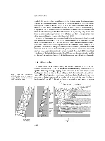
were outlined in section 12.4.8. The longitudinal sublevel caving method was devel-
oped for the mining of steeply dipping, narrow orebodies. In this case, the production
headings are driven on strike as shown in Figure 15.20. For wider orebodies, a trans-
Figure 15.20 Early longitudinal verse sublevel caving method may be used with the production headings being driven
sublevel caving layout for a narrow,
steeply dipping orebody of varying across the orebody from footwall to hangingwall as shown in the generalised min-
width (after Sarin, 1981). ing layout in Figure 12.13. The choice between longitudinal and transverse layouts
453