
Page 47 - Rock Mechanics For Underground Mining
P. 47
DISPLACEMENT AND STRAIN
Substitution of the magnitudes 1 , 2 , determined from equation 2.24a, in equation
2.24b yields the orientations 1 , 2 of the principal stress axes relative to the positive
direction of the x axis. Calculation of the orientations of the major and minor plane
principal stresses in this way associates a principal stress axis unambiguously with
a principal stress magnitude. This is not the case with other methods, which employ
the last of equations 2.23 to determine the orientation of a principal stress axis.
It is to be noted that in specifying the state of stress in a body, there has been no
reference to any mechanical properties of the body which is subject to applied load.
The only concept invoked has been that of static equilibrium of all elements of the
body.
2.7 Displacement and strain
Application of a set of forces to a body, or change in its temperature, changes the
relative positions of points within it. The change in loading conditions from the initial
state to the final state causes a displacement of each point relative to all other points.
If the applied loads constitute a self-equilibrating set, the problem is to determine
the equilibrium displacement field induced in the body by the loading. A particu-
lar difficulty is presented in the analysis of displacements for a loaded body where
boundary conditions are specified completely in terms of surface tractions. In this
case, unique determination of the absolute displacement field is impossible, since any
set of rigid-body displacements can be superimposed on a particular solution, and
still satisfy the equilibrium condition. Difficulties of this type are avoided in analysis
by employing displacement gradients as the field variables. The related concept of
strain is therefore introduced to make basically indeterminate problems tractable.
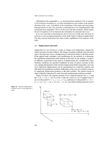
Figure 2.6 shows the original positions of two adjacent particles P(x, y, z) and
Q(x + dx, y + dy, z + dz) in a body. Under the action of a set of applied loads, P
∗ ∗
moves to the point P (x + u x , y + u y , z + u z ), and Q moves to the point Q (x + dx +
∗
∗
∗
∗
u , y + dy + u , z + dz + u ). If u x = u , etc., the relative displacement between P
x y z x
Figure 2.6 Initial and final positions
of points P, Q, in a body subjected to
strain.
29