
Page 532 - Rock Mechanics For Underground Mining
P. 532
MINING-INDUCED SURFACE SUBSIDENCE
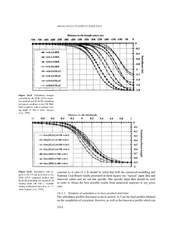
Figure 16.25 Subsidence troughs
predicted by the NCB (1975) empir-
ical method and FLAC2D modelling
for typical conditions in the UK Mid-
lands coalfields with a constant min-
ing depth of 300 m (after Alejano
et al., 1999).
Figure 16.26 Subsidence with re- constant w/h ratio of 2. It should be noted that both the numerical modelling and
spect to the rib side predicted by the
National Coal Board results presented in these figures use “typical” input data and
NCB (1975) empirical method and
observed values and are not site specific. Site specific input data should be used
FLAC2D modelling for longwalls of
in order to obtain the best possible results from numerical analyses of any given
varying depth but with a constant
mining width/depth ratio of w/h = 2 case.
(after Alejano et al., 1999).
16.5.5 Relation of subsidence to face position and time
The subsidence profiles discussed so far in section 16.5 are the final profiles attained
on the completion of extraction. However, as well as the transverse profile which can
514