
Page 127 - Root Cause Failure Analysis
P. 127
Conveyors 115
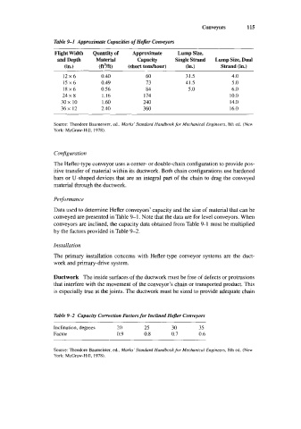
Table %I Approximate Capacities of Hejler Conveyors
Flight Width Quantity of Approximate Lump Size,
and Depth Material Capacity Single Strand Lump Size, Dual
(in.) cftm (short tonshour) (in.) Strand (in.)
12x6 0.40 60 31.5 4.0
15x6 0.49 13 41.5 5 .O
18x6 0.56 84 5.0 6.0
24 x 8 1.16 174 10.0
30x 10 1.60 240 14.0
36x 12 2.40 360 16.0
Source: Theodore Baumeister, ed.. Marks’ Standard Handbook for Mechanical Engineers, 8th ed. (New
York: McGraw-Hill. 1978).
Configuration
The Hefler-type conveyor uses a center- or double-chain configuration to provide pos-
itive transfer of material within its ductwork. Both chain configurations use hardened
bars or U-shaped devices that are an integral part of the chain to drag the conveyed
material through the ductwork.
Peqonnance
Data used to determine Hefler conveyors’ capacity and the size of material that can be
conveyed are presented in Table 9-1. Note that the data are for level conveyors. When
conveyors are inclined, the capacity data obtained from Table 9-1 must be multiplied
by the factors provided in Table 9-2.
Installation
The primary installation concerns with Hefler-type conveyor systems are the duct-
work and primary-drive system.
Ductwork The inside surfaces of the ductwork must be free of defects or protrusions
that interfere with the movement of the conveyor’s chain or transported product. This
is especially true at the joints. The ductwork must be sized to provide adequate chain
Table 9-2 Capac?y Correction Factors for Inclined Hefler Conveyors
Inclination, degrees 20 25 30 35
Factor 0.9 0.8 0.7 0.6
Source: Theodore Baumeister, ed.. Marks’ Standard Handbook for Mechanical Engineers, 8th ed. (New
York: McCraw-Hill, 1978).