
Page 173 - Root Cause Failure Analysis
P. 173
Dust Collectors 161
Configuration
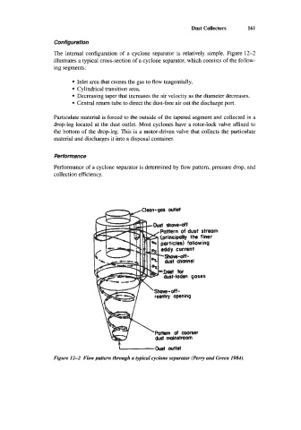
The internal configuration of a cyclone separator is relatively simple. Figure 12-2
illustrates a typical cross-section of a cyclone separator, which consists of the follow-
ing segments:
Inlet area that causes the gas to flow tangentially,
Cylindrical transition area,
Decreasing taper that increases the air velocity as the diameter decreases,
Central return tube to direct the dust-free air out the discharge port.
Particulate material is forced to the outside of the tapered segment and collected in a
drop-leg located at the dust outlet. Most cyclones have a rotor-lock valve affixed to
the bottom of the drop-leg. This is a motor-driven valve that collects the particulate
material and discharges it into a disposal container.
performance
Performance of a cyclone separator is determined by flow pattern, pressure drop, and
collection efficiency.
L O w f outlet
Figure 12-2 Flow pattern through a lypical cyclone separator (Perry and Green 1984).