
Page 237 - Root Cause Failure Analysis
P. 237
seals and Packing 225
8. Continue to remove the rest of the packing rings as previously described.
Keep each ring and note the sequence that it was removed.
9. Do not discard packing rings until they have been thoroughly examined for
potential problems.
10. Turn on the gland seal cooling water slightly to ensure there is no blockage
in the line. Shut the valve when good flow conditions are established.
11. Repeat Steps 1 through 10 with the other gland box.
12. Carefully clean out the gland-stuffing boxes with a solvent-soaked rag to
ensure that no debris is left behind.
13. Examine the shaft sleeve in both gland areas for excessive wear caused by
poorly lubricated or overtightened packing. NOTE: If the shaft sleeve is
ridged or badly scratched in any way, the split housing of the pump may
have to be taken apart and the impeller removed for the sleeve to be
replaced. This is caused by badly installed and maintained packing.
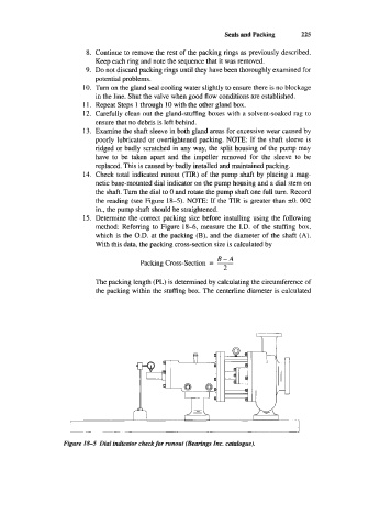
14. Check total indicated runout (TIR) of the pump shaft by placing a mag-
netic base-mounted dial indicator on the pump housing and a dial stem on
the shaft. Turn the dial to 0 and rotate the pump shaft one full turn. Record
the reading (see Figure 18-5). NOTE: If the TIR is greater than k0. 002
in., the pump shaft should be straightened.
15. Determine the correct packing size before installing using the following
method: Referring to Figure 18-6, measure the I.D. of the stuffing box,
which is the O.D. at the packing (B), and the diameter of the shaft (A).
With this data, the packing cross-section size is calculated by
B-A
Packing Cross-Section = -
2
The packing length (PL) is determined by calculating the circumference of
the packing within the stuffing box. The centerline diameter is calculated
I
I
1
Figure 18-5 Dial indicator check for runout (Bearings Inc. cataIogue).