
Page 247 - Root Cause Failure Analysis
P. 247
Seals and Packing 235
that, if the temperature of the fluid is above its saturation point at atmospheric pres-
sure, it flashes off to vapor before it can be visually detected.
Friction Drive or Single-Coil Spring Seal
The seal shown back in Figure 18-2 is a typical friction drive, or single-coil spring
seal unit. This design is limited in use to nonlubricating fluids (e.g., water) because it
relies on friction to turn the rotary unit. For use with liquids that have natural lubricat-
ing properties. the seal must be mechanically locked to the drive shaft.
Two drawbacks must be considered for this type of seal. Both are related to the use of
a coil spring that fits over the drive shaft. Nevertheless, the simple and reliable coil
spring seal has proven itself in the pumping industry and often is specified despite its
drawbacks. In regulated industries, this type of seal design far exceeds the capabilities
of a compressed packing ring seal.
One drawback of the spring seal is the need for relatively low shaft speeds. The com-
ponents have a tendency to distort at high surface speeds. This makes the spring push
harder on one side of the seal than the other, resulting in an uneven liquid film
between the faces, which causes excessive leakage and wear at the seal.
The other drawback is simply one of economics. Because pumps come in a variety of
shaft sizes and speeds, the use of this type of seal requires several sizes of spare
springs be kept in inventory.
Positive Drive
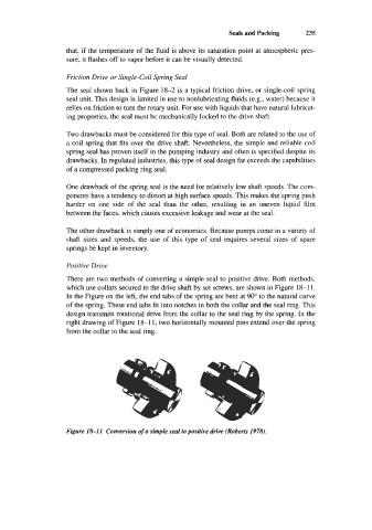
There are two methods of converting a simple seal to positive drive. Both methods,
which use collars secured to the drive shaft by set screws, are shown in Figure 18-1 1.
In the Figure on the left, the end tabs of the spring are bent at 90" to the natural curve
of the spring. These end tabs fit into notches in both the collar and the seal ring. This
design transmits rotational drive from the collar to the seal ring by the spring. In the
right drawing of Figure 18-1 1, two horizontally mounted pins extend over the spring
from the collar to the seal ring.
Figure 18-11 Conversion of a simple seal to positive drive (Roberts 1978).