
Page 72 - Rotating Machinery Pratical Solutions to Unbalance and Misalignment
P. 72
Rotating Machinery: Practical Solutions
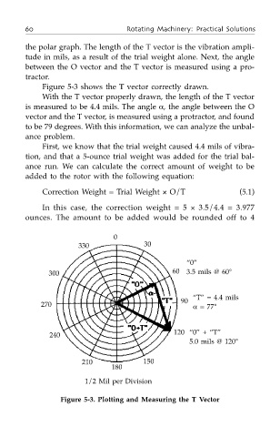
the polar graph. The length of the T vector is the vibration ampli-
tude in mils, as a result of the trial weight alone. Next, the angle
between the O vector and the T vector is measured using a pro-
tractor.
Figure 5-3 shows the T vector correctly drawn.
With the T vector properly drawn, the length of the T vector
is measured to be 4.4 mils. The angle α, the angle between the O
vector and the T vector, is measured using a protractor, and found
to be 79 degrees. With this information, we can analyze the unbal-
ance problem.
First, we know that the trial weight caused 4.4 mils of vibra-
tion, and that a 5-ounce trial weight was added for the trial bal-
ance run. We can calculate the correct amount of weight to be
added to the rotor with the following equation:
Correction Weight = Trial Weight × O/T (5.1)
In this case, the correction weight = 5 × 3.5/4.4 = 3.977
ounces. The amount to be added would be rounded off to 4
0
330 30
“0”
300 60 3.5 mils @ 60°
“T” = 4.4 mils
90
270 α = 77°
240 120 “0” + “T”
5.0 mils @ 120°
210 150
180
1/2 Mil per Division
Figure 5-3. Plotting and Measuring the T Vector