
Page 204 - Satellite Communications, Fourth Edition
P. 204
184 Chapter Six
l 1
Input Output
l 2
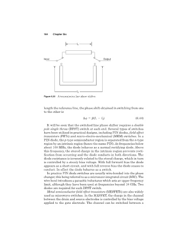
Figure 6.35 A transmission line phase shifter.
length the reference line, the phase shift obtained in switching from one
to the other is
l ) (6.44)
(l 1 2
It will be seen that the switched line phase shifter requires a double
pole single throw (DPST) switch at each end. Several types of switches
have been utilized in practical designs, including PIN diodes, field effect
transistors (FETs) and micro-electro-mechanical (MEM) switches. In a
PIN diode, the p-type semiconductor region is separated from the n-type
region by an intrinsic region (hence the name PIN). At frequencies below
about 100 MHz, the diode behaves as a normal rectifying diode. Above
this frequency, the stored charge in the intrinsic region prevents recti-
fication from occurring and the diode conducts in both directions. The
diode resistance is inversely related to the stored charge, which in turn
is controlled by a steady bias voltage. With full forward bias the diode
appears as a short circuit, and with full reverse bias the diode ceases to
conduct. In effect the diode behaves as a switch.
In practice PIN diode switches are usually wire-bonded into the phase
changer, this being referred to as a microwave integrated circuit (MIC). The
wire bond introduces a parasitic inductance which sets an upper frequency
limit, although they have been used at frequencies beyond 18 GHz. Two
diodes are required for each DPST switch.
Metal semiconductor field effect transistors (MESFETs) are also widely
used as microwave switches. In the MESFET, the charge in the channel
between the drain and source electrodes is controlled by the bias voltage
applied to the gate electrode. The channel can be switched between a