
Page 274 - Satellite Communications, Fourth Edition
P. 274
254 Chapter Nine
to as a voice frequency (VF) channel, and in this book this will be taken
to mean the frequency range of 300 to 3400 Hz.
There are good reasons for limiting the frequency range. Noise, which
covers a very wide frequency spectrum, is reduced by reducing the band-
width. Also, reducing the bandwidth allows more telephone channels to
be carried over a given type of circuit, as will be described in Sec. 9.4.
The signal levels encountered within telephone networks vary con-
siderably. Audio signal levels are often measured in volume units (VU).
For a sinusoidal signal within the VF range, 0 VU corresponds to 1 mW
of power, or 0 dBm. No simple relationship exists between VU and power
for speech signals, but as a rough guide, the power level in dBm of
normal speech is given by VU −1.4. As a rule of thumb, the average voice
level on a telephone circuit (or mean talker level) is defined as 13 VU
(see Freeman, 1981).
9.3 Single-Sideband Telephony
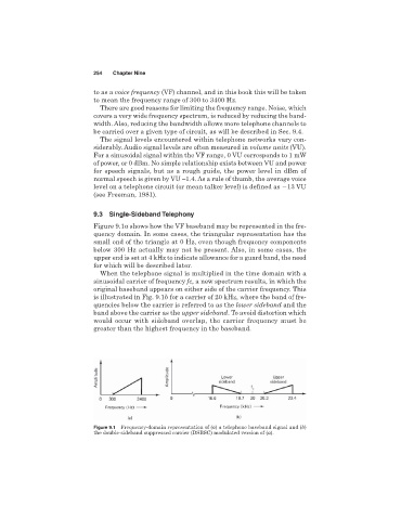
Figure 9.1a shows how the VF baseband may be represented in the fre-
quency domain. In some cases, the triangular representation has the
small end of the triangle at 0 Hz, even though frequency components
below 300 Hz actually may not be present. Also, in some cases, the
upper end is set at 4 kHz to indicate allowance for a guard band, the need
for which will be described later.
When the telephone signal is multiplied in the time domain with a
sinusoidal carrier of frequency fc, a new spectrum results, in which the
original baseband appears on either side of the carrier frequency. This
is illustrated in Fig. 9.1b for a carrier of 20 kHz, where the band of fre-
quencies below the carrier is referred to as the lower sideband and the
band above the carrier as the upper sideband. To avoid distortion which
would occur with sideband overlap, the carrier frequency must be
greater than the highest frequency in the baseband.
Figure 9.1 Frequency-domain representation of (a) a telephone baseband signal and (b)
the double-sideband suppressed carrier (DSBSC) modulated version of (a).