
Page 275 - Satellite Communications, Fourth Edition
P. 275
Analog Signals 255
The result of this multiplication process is referred to as double-sideband
suppressed-carrier (DSBSC) modulation, since only the sidebands, and
not the carrier, appear in the spectrum. Now, all the information in the orig-
inal telephone signal is contained in either of the two sidebands, and
therefore, it is necessary to transmit only one of these. Afilter may be used
to select either one and reject the other. The resulting output is termed a
single-sideband (SSB) signal.
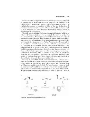
The SSB process utilizing the lower sideband is illustrated in Fig. 9.2,
where a 20-kHz carrier is used as an example. It will be seen that for
the lower sideband, the frequencies have been inverted, the highest
baseband frequency being translated to the lowest transmission fre-
quency at 16.6 kHz and the lowest baseband frequency to the high-
est transmission frequency at 19.7 kHz. This inversion does not affect
the final baseband output, since the demodulation process reinverts
the spectrum. At the receiver, the SSB signal is demodulated (i.e., the
baseband signal is recovered) by being passed through an identical
multiplying process. In this case the multiplying sinusoid, termed the
local oscillator (LO) signal, must have the same frequency as the orig-
inal carrier. A low-pass filter is required at the output to select the
baseband signal and reject other, unwanted frequency components gen-
erated in the demodulation process. This single-sideband modulation/
demodulation process is illustrated in Fig. 9.2.
The way in which SSB signals are used for the simultaneous trans-
mission of a number of telephone signals is described in the following sec-
tion. It should be noted at this point that a number of different carriers
are likely to be used in a satellite link. The radiofrequency (rf) carrier used
in transmission to and from the satellite will be much higher in fre-
quency than those used for the generation of the set of SSB signals.
These latter carriers are sometimes referred to as VF carriers. The term
Figure 9.2 A basic SSB transmission scheme.