
Page 285 - Satellite Communications, Fourth Edition
P. 285
Analog Signals 265
digital intercontinental conversion equipment (DICE), is favored
because of its good performance and lower cost (see Miya, 1981).
9.6 Frequency Modulation
The analog signals discussed in the previous sections are transferred to
the microwave carrier by means of FM. Instead of being done in one step,
as shown in Fig. 9.8b, this modulation usually takes place at an inter-
mediate frequency, as shown in Fig. 8.6. This signal is then frequency
multiplied up to the required uplink microwave frequency. In the receive
branch of Fig. 8.6, the incoming (downlink) FM microwave signal is
downconverted to an intermediate frequency, and the baseband signal
is recovered from the intermediate frequency (IF) carrier in the demod-
ulator. The actual baseband video signal is now available directly via a
low-pass filter, but the audio channels must each undergo an additional
step of FM demodulation to recover the baseband audio signals.
A major advantage associated with FM is the improvement in the
postdetection signal-to-noise ratio at the receiver output compared with
other analog modulation methods. This improvement can be attributed
to three factors:
1. Amplitude limiting
2. A property of FM which allows an exchange between signal-to-noise
ratio and bandwidth
3. A noise reduction inherent in the way noise phase modulates a carrier
These factors are discussed in more detail in the following sections.
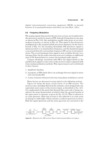
Figure 9.9 shows the basic circuit blocks of an FM receiver. The
receiver noise, including that from the antenna, can be lumped into one
equivalent noise source at the receiver input, as described in Sec. 12.5.
It is emphasized at this point that thermal-like noise only is being con-
sidered, the main characteristic of which is that the spectral density of
the noise power is constant, as given by Eq. (12.15). This is referred to
as a flat spectrum. (This type of noise is also referred to as white noise
in analogy to white light, which contains a uniform spectrum of colors.)
Both the signal spectrum and the noise spectrum are converted to the
Figure 9.9 Elements of an FM receiver. Figures shown in parentheses are typical.