
Page 289 - Satellite Communications, Fourth Edition
P. 289
Analog Signals 269
is possible but at the expense of an increase in the IF bandwidth. This
is the large-amplitude signal improvement referred to in Sec. 9.6 and
considered further in the following section.
9.6.3 FM detector noise
and processing gain
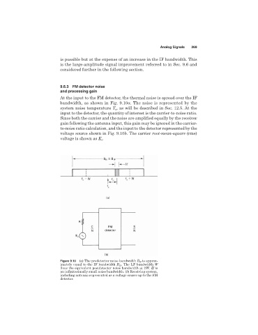
At the input to the FM detector, the thermal noise is spread over the IF
bandwidth, as shown in Fig. 9.10a. The noise is represented by the
system noise temperature T , as will be described in Sec. 12.5. At the
s
input to the detector, the quantity of interest is the carrier-to-noise ratio.
Since both the carrier and the noise are amplified equally by the receiver
gain following the antenna input, this gain may be ignored in the carrier-
to-noise ratio calculation, and the input to the detector represented by the
voltage source shown in Fig. 9.10b. The carrier root-mean-square (rms)
voltage is shown as E .
c
Figure 9.10 (a) The predetector noise bandwidth B N is approx-
imately equal to the IF bandwidth B IF . The LF bandwidth W
fixes the equivalent postdetector noise bandwidth at 2W. df is
an infinitesimally small noise bandwidth. (b) Receiving system,
including antenna represented as a voltage source up to the FM
detector.