
Page 375 - Satellite Communications, Fourth Edition
P. 375
The Space Link 355
feeder losses. The [RFL] values are added to [FSL] in Eq. (12.11). Similar
losses will occur in the filters, couplers, and waveguides connecting
the transmit antenna to the high-power amplifier (HPA) output.
However, provided that the EIRP is stated, Eq. (12.11) can be used
without knowing the transmitter feeder losses. These are needed only
when it is desired to relate EIRP to the HPA output, as described in
Secs. 12.7.4 and 12.8.2.
12.3.3 Antenna misalignment losses
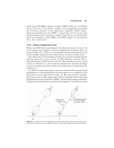
When a satellite link is established, the ideal situation is to have the
earth station and satellite antennas aligned for maximum gain, as
shown in Fig. 12.1a. There are two possible sources of off-axis loss, one
at the satellite and one at the earth station, as shown in Fig. 12.1b.
The off-axis loss at the satellite is taken into account by designing the
link for operation on the actual satellite antenna contour; this is
described in more detail in later sections. The off-axis loss at the earth
station is referred to as the antenna pointing loss. Antenna pointing
losses are usually only a few tenths of a decibel; typical values are given
in Table 12.1.
In addition to pointing losses, losses may result at the antenna from
misalignment of the polarization direction (these are in addition to the
polarization losses described in Chap. 5). The polarization misalign-
ment losses are usually small, and it will be assumed that the antenna
misalignment losses, denoted by [AML], include both pointing and polar-
ization losses resulting from antenna misalignment. It should be noted
Figure 12.1 (a) Satellite and earth-station antennas aligned for maximum gain; (b) earth
station situated on a given satellite “footprint,” and earth-station antenna misaligned.