
Page 380 - Satellite Communications, Fourth Edition
P. 380
360 Chapter Twelve
about 1 and 10 GHz. This represents the residual background radiation
in the universe. Above about 10 GHz, two peaks in temperature are
observed, resulting from resonant losses in the earth’s atmosphere.
These are seen to coincide with the peaks in atmospheric absorption loss
shown in Fig. 4.2.
Any absorptive loss mechanism generates thermal noise, there being a
direct connection between the loss and the effective noise temperature, as
shown in Sec. 12.5.5. Rainfall introduces attenuation, and therefore, it
degrades transmissions in two ways: It attenuates the signal, and it intro-
duces noise. The detrimental effects of rain are much worse at Ku-band
frequencies than at C band, and the downlink rain-fade margin, discussed
in Sec. 12.9.2, must also allow for the increased noise generated.
Figure 12.2 applies to ground-based antennas. Satellite antennas are
generally pointed toward the earth, and therefore, they receive the full
thermal radiation from it. In this case the equivalent noise temperature
of the antenna, excluding antenna losses, is approximately 290 K.
Antenna losses add to the noise received as radiation, and the total
antenna noise temperature is the sum of the equivalent noise tempera-
tures of all these sources. For large ground-based C-band antennas, the
total antenna noise temperature is typically about 60 K, and for the Ku
band, about 80 K under clear-sky conditions. These values do not apply
to any specific situation and are quoted merely to give some idea of the
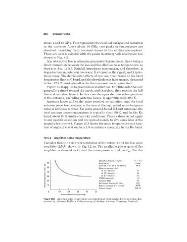
magnitudes involved. Figure 12.3 shows the noise temperature as a func-
tion of angle of elevation for a 1.8-m antenna operating in the Ku band.
12.5.2 Amplifier noise temperature
Consider first the noise representation of the antenna and the low noise
amplifier (LNA) shown in Fig. 12.4a. The available power gain of the
amplifier is denoted as G, and the noise power output, as P . For the
no
Figure 12.3 Antenna noise temperature as a function of elevation for 1.8-m antenna char-
acteristics. (Andrew Bulletin 1206; courtesy of Andrew Antenna Company, Limited.)