
Page 381 - Satellite Communications, Fourth Edition
P. 381
The Space Link 361
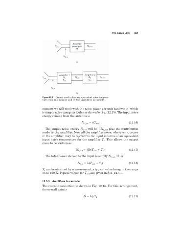
Figure 12.4 Circuit used in finding equivalent noise tempera-
ture of (a) an amplifier and (b) two amplifiers in cascade.
moment we will work with the noise power per unit bandwidth, which
is simply noise energy in joules as shown by Eq. (12.15). The input noise
energy coming from the antenna is
N 0,ant kT ant (12.16)
The output noise energy N 0,out will be GN 0,ant plus the contribution
made by the amplifier. Now all the amplifier noise, wherever it occurs
in the amplifier, may be referred to the input in terms of an equivalent
input noise temperature for the amplifier T . This allows the output
e
noise to be written as
N 0,out Gk(T ant T ) (12.17)
e
The total noise referred to the input is simply N 0,out /G,or
N 0,in k(T ant T ) (12.18)
e
T can be obtained by measurement, a typical value being in the range
e
35 to 100 K. Typical values for T ant are given in Sec. 12.5.1.
12.5.3 Amplifiers in cascade
The cascade connection is shown in Fig. 12.4b. For this arrangement,
the overall gain is
G G G 2 (12.19)
1