
Page 446 - Satellite Communications, Fourth Edition
P. 446
426 Chapter Fourteen
access a single satellite transponder channel simultaneously, and each
communicates with both of the others. Thus it is assumed that the satel-
lite receive and transmit antenna beams are global, encompassing all
three earth stations. Each earth station transmits one uplink carrier
modulated with a 60-channel supergroup and receives two similar down-
link carriers.
The earth station at New York is shown in more detail. One transmit
chain is used, and this carries telephone traffic for both Ottawa and
London. On the receive side, two receive chains must be provided, one
for the Ottawa-originated carrier and one for the London-originated
carrier. Each of these carriers will have a mixture of traffic, and in the
demultiplexing unit, only those telephone channels intended for New
York are passed through. These are remultiplexed into an FDM/FM
format which is transmitted out along the terrestrial line to the New
York switching office. This earth-station arrangement should be com-
pared with that shown in Fig. 8.6.
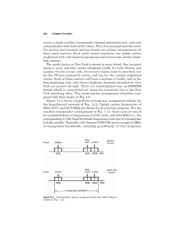
Figure 14.3 shows a hypothetical frequency assignment scheme for
the hypothetical network of Fig. 14.2. Uplink carrier frequencies of
6253, 6273, and 6278 MHz are shown for illustration purposes. For the
satellite transponder arrangement of Fig. 7.13, these carriers would
be translated down to frequencies of 4028, 4048, and 4053 MHz (i.e., the
corresponding 4-GHz-band downlink frequencies) and sent to transponder
9 of the satellite. Typically, a 60-channel FDM/FM carrier occupies 5 MHz
of transponder bandwidth, including guardbands. A total frequency
Figure 14.3 Transponder channel assignments for the earth stations
shown in Fig. 14.2.