
Page 314 - Schaum's Outline of Theory and Problems of Applied Physics
P. 314
CHAP. 25] DIRECT-CURRENTCIRCUITS 299
In the case of the circuit shown in Fig. 25-9, Kirchhoff’s first rule, applied to either junction a or junction b,
yields
I 1 = I 2 + I 3
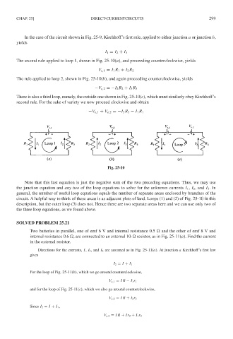
The second rule applied to loop 1, shown in Fig. 25-10(a), and proceeding counterclockwise, yields
V e,1 = I 1 R 1 + I 2 R 2
The rule applied to loop 2, shown in Fig. 25-10(b), and again proceeding counterclockwise, yields
−V e,2 =−I 2 R 2 + I 3 R 3
There is also a third loop, namely, the outside one shown in Fig. 25-10(c), which must similarly obey Kirchhoff’s
second rule. For the sake of variety we now proceed clockwise and obtain
−V e,1 + V e,2 =−I 3 R 3 − I 1 R 1
Fig. 25-10
Note that this last equation is just the negative sum of the two preceding equations. Thus, we may use
the junction equation and anytwo of the loop equations to solve for the unknown currents I 1 , I 2 , and I 3 .In
general, the number of useful loop equations equals the number of separate areas enclosed by branches of the
circuit. A helpful way to think of these areas is as adjacent plots of land. Loops (1) and (2) of Fig. 25-10 fit this
description, but the outer loop (3) does not. Hence there are two separate areas here and we can use only two of
the three loop equations, as we found above.
SOLVED PROBLEM 25.21
Two batteries in parallel, one of emf 6 V and internal resistance 0.5 and the other of emf8Vand
internal resistance 0.6 , are connected to an external 10- resistor, as in Fig. 25-11(a). Find the current
in the external resistor.
Directions for the currents, I, I 1 , and I 2 are assumed as in Fig. 25-11(a). At junction a Kirchhoff’s first law
gives
I 2 = I + I 1
For the loop of Fig. 25-11(b), which we go around counterclockwise,
V e,1 = IR − I 1 r 1
and for the loop of Fig. 25-11(c), which we also go around counterclockwise,
V e,2 = IR + I 2 r 2
Since I 2 = I + I 1 ,
V e,2 = IR + Ir 2 + I 1 r 2