
Page 426 - Schaum's Outline of Theory and Problems of Applied Physics
P. 426
CHAP. 33] PHYSICAL AND QUANTUM OPTICS 411
A
S B D
C
S¢
(a)
Constructive interference
produces bright line
D
Destructive interference
C produces dark line
A
S Constructive interference
produces bright line
S¢
B
(b)
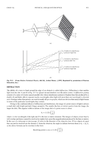
Fig. 33-3. (From Modern Technical Physics, 6th Ed., Arthur Beiser, c 1992. Reprinted by permission of Pearson
Education, Inc.)
DIFFRACTION
The ability of a wave to bend around the edge of an obstacle is called diffraction. Diffraction is what enables
light from the slits A and B in Fig. 33-3 to spread out and interfere over the entire screen. A diffraction grating
consists of a series of closely-spaced parallel slits whose interference pattern is brighter than that produced by a
double slit and better able to separate nearby wavelengths when light with more than one wavelength is directed
on it. Gratings rather than prisms, are used in nearly all spectrographs, which are devices that analyze light beams
in terms of the particular wavelengths they contain.
Owing to the combined effects of diffraction and interference, the image of a point source of light is always
a small disk with bright and dark fringes around it. The smaller the lens or mirror used to form the image, the
larger the disk. The angular width in radians of the image disk of a point source is about
λ
θ 0 = (1.22)
D
where λ is the wavelength of the light and D is the lens or mirror diameter. The images of objects closer than θ 0
will overlap and hence cannot be resolved no matter how great the magnification produced by the lens or mirror.
In the case of a telescope or microscope, D refers to the diameter of the objective lens. If two objects d 0 apart
that can just be resolved are the distance L from the observer, the angle in radians between them is θ 0 = d 0 /L,
so the above formula can be rewritten in the form
λL
Resolving power = d 0 = (1.22)
D