
Page 36 - Schaum's Outline of Theory and Problems of Electric Circuits
P. 36
CIRCUIT LAWS
CHAP. 3]
Starting at the lower left corner of the circuit, for the current direction as shown, we have 25
v a þ v 1 þ v b þ v 2 þ v 3 ¼ 0
v a þ iR 1 þ v b þ iR 2 þ iR 3 ¼ 0
v a v b ¼ iðR 1 þ R 2 þ R 3 Þ
3.3 KIRCHHOFF’S CURRENT LAW
The connection of two or more circuit elements creates a junction called a node. The junction
between two elements is called a simple node and no division of current results. The junction of three or
more elements is called a principal node, and here current division does take place. Kirchhoff’s current
law (KCL) states that the algrebraic sum of the currents at a node is zero. It may be stated alternatively
that the sum of the currents entering a node is equal to the sum of the currents leaving that node. The
node voltage method of circuit analysis introduced in Section 4.3 is based on equations written at the
principal nodes of a network by applying Kirchhoff’s current law. The basis for the law is the con-
servation of electric charge.
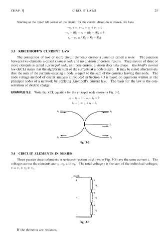
EXAMPLE 3.2. Write the KCL equation for the principal node shown in Fig. 3-2.
i 1 i 2 þ i 3 i 4 i 5 ¼ 0
i 1 þ i 3 ¼ i 2 þ i 4 þ i 5
Fig. 3-2
3.4 CIRCUIT ELEMENTS IN SERIES
Three passive circuit elements in series connection as shown in Fig. 3-3 have the same current i. The
voltages across the elements are v 1 , v 2 , and v 3 . The total voltage v is the sum of the individual voltages;
v ¼ v 1 þ v 2 þ v 3 .
Fig. 3-3
If the elements are resistors,