
Page 39 - Schaum's Outline of Theory and Problems of Electric Circuits
P. 39
28
3.6 VOLTAGE DIVISION CIRCUIT LAWS [CHAP. 3
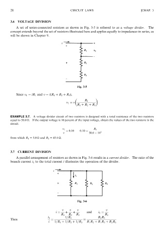
A set of series-connected resistors as shown in Fig. 3-5 is referred to as a voltage divider. The
concept extends beyond the set of resistors illustrated here and applies equally to impedances in series, as
will be shown in Chapter 9.
Fig. 3-5
Since v 1 ¼ iR 1 and v ¼ iðR 1 þ R 2 þ R 3 Þ,
R 1
v 1 ¼ v
R þ R þ R 3
1
2
EXAMPLE 3.7. A voltage divider circuit of two resistors is designed with a total resistance of the two resistors
equal to 50.0
. If the output voltage is 10 percent of the input voltage, obtain the values of the two resistors in the
circuit.
v 1 R 1
¼ 0:10 0:10 ¼
v 50:0 10 3
from which R 1 ¼ 5:0
and R 2 ¼ 45:0
.
3.7 CURRENT DIVISION
A parallel arrangement of resistors as shown in Fig. 3-6 results in a current divider. The ratio of the
branch current i 1 to the total current i illustrates the operation of the divider.
Fig. 3-6
v v v v
i ¼ þ þ and i 1 ¼
R 1 R 2 R 3 R 1
i 1 1=R 1 R 2 R 3
Then ¼ ¼
i 1=R 1 þ 1=R 2 þ 1=R 3 R 1 R 2 þ R 1 R 3 þ R 2 R 3