Page 42 - Schaum's Outline of Theory and Problems of Electric Circuits
P. 42

CIRCUIT LAWS
               CHAP. 3]


                                                        Fig. 3-11                                     31

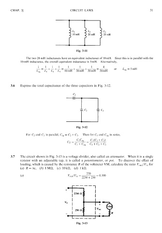
                         The two 20-mH inductances have an equivalent inductance of 10 mH.  Since this is in parallel with the
                     10-mH inductance, the overall equivalent inductance is 5 mH.  Alternatively,
                                1    1   1   1     1      1      1       4
                                  ¼    þ   þ   ¼      þ      þ       ¼          or   L eq ¼ 5mH
                               L eq  L 1  L 2  L 3  10 mH  20 mH  20 mH  20 mH


               3.6   Express the total capacitance of the three capacitors in Fig. 3-12.


                                                        Fig. 3-12

                         For C 2 and C 3 in parallel, C eq ¼ C 2 þ C 3 .  Then for C 1 and C eq in series,
                                                        C 1 C eq  C 1 ðC 2 þ C 3 Þ
                                                  C T ¼       ¼
                                                       C 1 þ C eq  C 1 þ C 2 þ C 3


               3.7   The circuit shown in Fig. 3-13 is a voltage divider, also called an attenuator. When it is a single
                     resistor with an adjustable tap, it is called a potentiometer,or pot.  To discover the effect of
                     loading, which is caused by the resistance R of the voltmeter VM, calculate the ratio V out =V in for
                     (a) R ¼1,(b)1 M
,      (c)10 k
,(d)1 k
.
                                                              250
                     ðaÞ                           V out =V in ¼    ¼ 0:100
                                                            2250 þ 250


                                                        Fig. 3-13
   37   38   39   40   41   42   43   44   45   46   47