
Page 241 - Schaum's Outline of Theory and Problems of Signals and Systems
P. 241
230 FOURIER ANALYSIS OF TIME SIGNALS AND SYSTEMS [CHAP. 5
which are plotted in Fig. 5-6(b). From Fig. 5-6(b) we see that the RC network in
Fig. 5-6(a) performs as a low-pass filter.
5.7 BANDWIDTH
A. Filter (or System) Bandwidth:
One important concept in system analysis is the bandwidth of an LTI system. There are
many different definitions of system bandwidth.
I. Absolute Bandwidth:
The bandwidth WB of an ideal low-pass filter equals its cutoff frequency; that is,
WB = w, [Fig. 5-5(a)]. In this case W, is called the absolute bandwidth. The absolute
bandwidth of an ideal bandpass filter is given by W, = w2 - w, [Fig. 5-5(c)]. A bandpass
filter is called narrowband if W, << w,, where w,, = ;( w, + w2) is the center frequency of
the filter. No bandwidth is defined for a high-pass or a bandstop filter.
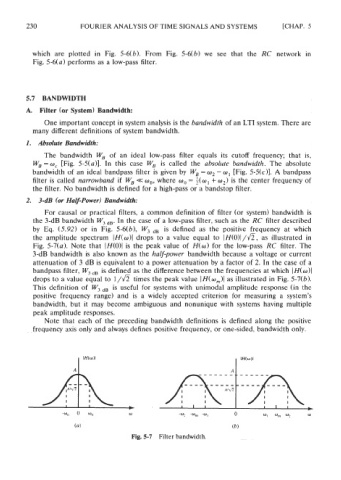
2. 3-dB (or Half-Power) Bandwidth:
For causal or practical filters, a common definition of filter (or system) bandwidth is
the 3-dB bandwidth W, ,,. In the case of a low-pass filter, such as the RC filter described
by Eq. (5.92) or in Fig. 5-6(b), W, ,, is defined as the positive frequency at which
the amplitude spectrum IH(w)l drops to a value equal to I H(o)I/~, as illustrated in
Fig. 5-7(a). Note that (H(O)I is the peak value of H(o) for the low-pass RC filter. The
3-dB bandwidth is also known as the half-power bandwidth because a voltage or current
attenuation of 3 dB is equivalent to a power attenuation by a factor of 2. In the case of a
bandpass filter, W, ,, is defined as the difference between the frequencies at which )H(w)l
drops to a value equal to 1/a times the peak value IH(w,)l as illustrated in Fig. 5-7(b).
This definition of W, ,, is useful for systems with unimodal amplitude response (in the
positive frequency range) and is a widely accepted criterion for measuring a system's
bandwidth, but it may become ambiguous and nonunique with systems having multiple
peak amplitude responses.
Note that each of the preceding bandwidth definitions is defined along the positive
frequency axis only and always defines positive frequency, or one-sided, bandwidth only.
(6)
Fig. 5-7 Filter bandwidth.