
Page 44 - Sensing, Intelligence, Motion : How Robots and Humans Move in an Unstructured World
P. 44
BASIC CONCEPTS 19
q 3
P (x, y, q )
3
P (x, y) l 3
y y
l 2 q 2 l 2 q 2
J 1 J 1
l 1 l 1
q 1 q
x 1 x
J o J o
(a) (b)
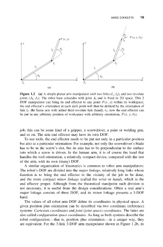
Figure 1.2 (a) A simple planar arm manipulator with two links (l 1 ,l 2 ), and two revolute
joints (J 0 ,J 1 ). The robot base coincides with joint J 0 and is fixed in 2D space. This 2
DOF manipulator can bring its end effector to any point P(x, y) within its workspace;
the end effector’s orientation at each such point will then be defined by the orientation of
link l 2 . (b) Same arm with added third revolute link (hand), l 3 ; now the end effector can
be put in any arbitrary position of workspace with arbitrary orientation, P(x, y, θ 3 ).
job; this can be some kind of a gripper, a screwdriver, a paint or welding gun,
and so on. The arm end effector may have its own DOF.
To use tools, the end effector needs to be put not only in a particular position
but also at a particular orientation: For example, not only the screwdriver’s blade
has to be in the screw’s slot, but its axis has to be perpendicular to the surface
into which a screw is driven. In the human arm, it is of course the hand that
handles the tool orientation, a relatively compact device, compared with the rest
of the arm, with its own (many) DOF.
A similar organization of kinematics is common to robot arm manipulators:
The robot’s DOF are divided into the major linkage, relatively long links whose
function is to bring the end effector to the vicinity of the job to be done,
and the more compact minor linkage (called the wrist or hand), which is the
end effector proper. Although from the theoretical standpoint such division is
not necessary, it is useful from the design considerations. Often a real arm’s
major linkage consists of three DOF, and its minor linkage presents a 3-DOF
hand.
The values of all robot arm DOF define its coordinates in physical space. A
given position plus orientation can be described via two coordinate (reference)
systems: Cartesian coordinates and joint (joint space) coordinates. The latter are
also called configuration space coordinates. As long as both systems describe the
robot configuration—that is, position plus orientation—in a unique way, they
are equivalent. For the 3-link 3-DOF arm manipulator shown in Figure 1.2b, its