Page 240 - Sensors and Control Systems in Manufacturing
P. 240

200
                           Cha p te r
                                    F o u r

                          an FMS, it was decided to divide development of the diagnostics pro-
                          gram into three major blocks (Fig. 4.2):
                              •  Analyzing the existing design
                              •  Setting up diagnostics that are machine-based
                              •  Choosing important points in the flexible manufacturing cells
                                 where critical failure can occur and where sensors are mounted
                              •  Setting up a diagnostic decision system for the hardware system
                              •  Establishing a workpiece-based diagnostic system that is
                                 actually part of quality control

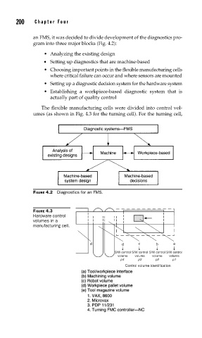
                             The flexible manufacturing cells were divided into control vol-
                          umes (as shown in Fig. 4.3 for the turning cell). For the turning cell,


                          FIGURE 4.2  Diagnostics for an FMS.


                          FIGURE 4.3
                          Hardware control
                          volumes in a
                          manufacturing cell.


                                                d           d      c      b     a
                                                          S/W control S/W control S/W control S/W control
                                                           volume  volume  volume  volume
                                                            p4     p3    p2     p1
                                                              Control volume identification
   235   236   237   238   239   240   241   242   243   244   245