Page 248 - Sensors and Control Systems in Manufacturing
P. 248

208
                           Cha p te r

                               User 2 F o u r                   User 1
                                                        Message         Confirmation
                                 7                                7     Application
                                                                           layer
                                 6                                6     Presentation
                                                 Peer                      layer
                                               raltionships
                                 5                                5      Session
                                                                           layer
                                 4                                4      Transport
                                                                           layer
                                 3                                3      Network
                                                                           layer
                                 2                                2      Data Link
                                                                           layer
                                 1                                1      Physical
                                                                           layer
                                                Medium


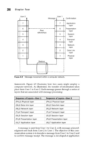
                          FIGURE 4.9  Message movement within a computer network.


                          framework. Figure 4.9 illustrates how two users might employ a
                          computer network. As illustrated, the transfer of information takes
                          place from User 1 to User 2. Each message passes through a series of
                          layers that are associated with message processing:


                           Sequence of Layers—User 1  Sequence of Layers—User 2
                           (PhL)1 Physical layer      (PhL)1 Physical layer
                           (DL)2 Data link layer      (DL)2 Data link layer
                           (NL)3 Network layer        (NL)3 Network layer
                           (TL)4 Transport layer      (TL)4 Transport layer
                           (SL)5 Session layer        (SL)5 Session layer
                           (PL)6 Presentation layer   (PL)6 Presentation layer
                           (AL)7 Application layer    (AL)7 Application layer

                             A message is sent from User 1 to User 2, with message acknowl-
                          edgment sent back from User 2 to User 1. The objective of this com-
                          munication system is to transfer a message from User 1 to User 2 and
                          to confirm message receipt. The message is developed at application
   243   244   245   246   247   248   249   250   251   252   253