
Page 178 - Separation process engineering
P. 178
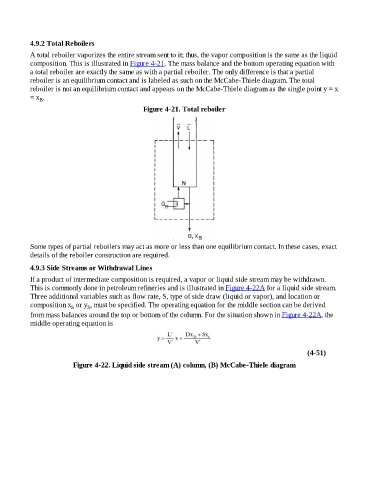
4.9.2 Total Reboilers

                    A total reboiler vaporizes the entire stream sent to it; thus, the vapor composition is the same as the liquid
                    composition. This is illustrated in Figure 4-21. The mass balance and the bottom operating equation with
                    a total reboiler are exactly the same as with a partial reboiler. The only difference is that a partial
                    reboiler is an equilibrium contact and is labeled as such on the McCabe-Thiele diagram. The total
                    reboiler is not an equilibrium contact and appears on the McCabe-Thiele diagram as the single point y = x
                    = x .
                        B
                                                                Figure 4-21. Total reboiler


                    Some types of partial reboilers may act as more or less than one equilibrium contact. In these cases, exact

                    details of the reboiler construction are required.

                    4.9.3 Side Streams or Withdrawal Lines
                    If a product of intermediate composition is required, a vapor or liquid side stream may be withdrawn.

                    This is commonly done in petroleum refineries and is illustrated in Figure 4-22A for a liquid side stream.
                    Three additional variables such as flow rate, S, type of side draw (liquid or vapor), and location or
                    composition x  or y , must be specified. The operating equation for the middle section can be derived
                                          S
                                    S
                    from mass balances around the top or bottom of the column. For the situation shown in Figure 4-22A, the
                    middle operating equation is


                                                                                                                                (4-51)

                                     Figure 4-22. Liquid side stream (A) column, (B) McCabe-Thiele diagram