
Page 180 - Separation process engineering
P. 180
4.9.4 Intermediate Reboilers and Intermediate Condensers
Another modification that is used occasionally is to have an intermediate reboiler or an intermediate
condenser. The intermediate reboiler removes a liquid side stream from the column, vaporizes it, and
reinjects the vapor into the column. An intermediate condenser removes a vapor side stream, condenses
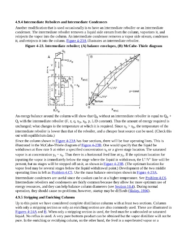
it, and reinjects it into the column. Figure 4-23A illustrates an intermediate reboiler.
Figure 4-23. Intermediate reboiler; (A) balance envelopes, (B) McCabe-Thiele diagram
An energy balance around the column will show that Q without an intermediate reboiler is equal to Q +
R R
Q with the intermediate reboiler (F, z, q, x , x , p, L/D constant). Thus the amount of energy required is
B
I
D
unchanged; what changes is the temperature at which it is required. Since x > x , the temperature of the
B
S
intermediate reboiler is lower than that of the reboiler, and a cheaper heat source can be used. (Check this
out with equilibrium data.)
Since the column shown in Figure 4-23A has four sections, there will be four operating lines. This is
illustrated in the McCabe-Thiele diagram of Figure 4-23B. One would specify that the liquid be
withdrawn at flow rate S at either a specified concentration x or a given stage location. The saturated
S
vapor is at concentration y = x . Thus there is a horizontal feed line at y . If the optimum location for
S
S
S
inputting the vapor is immediately below the stage where the liquid is withdrawn, the L″/V″ line will be
present, but no stages will be stepped off on it, as shown in Figure 4-23B. (The optimum location for
vapor feed may be several stages below the liquid withdrawal point.) Development of the two middle
operating lines is left as Problem 4.C5. Use the mass balance envelopes shown in Figure 4-23A.
Intermediate condensers are useful since the coolant can be at a higher temperature. See Problem 4.C6.
Intermediate reboilers and condensers are fairly common because they allow for more optimum use of
energy resources, and they can help balance column diameters (see Section 10.4). During normal
operation, they should cause no problems; however, startup may be difficult (Sloley, 1996).
4.9.5 Stripping and Enriching Columns
Up to this point we have considered complete distillation columns with at least two sections. Columns
with only a stripping section or only an enriching section are also commonly used. These are illustrated in
Figures 4-24A and B. When only a stripping section is used, the feed must be a subcooled or saturated
liquid. No reflux is used. A very pure bottoms product can be obtained but the vapor distillate will not be
pure. In the enriching or rectifying column, on the other hand, the feed is a superheated vapor or a