
Page 185 - Separation process engineering
P. 185
where is vapor mole fraction in equilibrium with actual liquid mole fraction x.
j
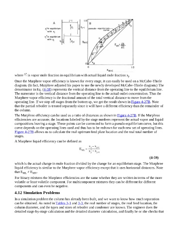
Once the Murphree vapor efficiency is known for every stage, it can easily be used on a McCabe-Thiele
diagram. (In fact, Murphree adjusted his paper to use the newly developed McCabe-Thiele diagram.) The
denominator in Eq. (4-58) represents the vertical distance from the operating line to the equilibrium line.
The numerator is the vertical distance from the operating line to the actual outlet concentration. Thus the
Murphree vapor efficiency is the fractional amount of the total vertical distance to move from the
operating line. If we step off stages from the bottom up, we get the result shown in Figure 4-27B. Note
that the partial reboiler is treated separately since it will have a different efficiency than the remainder of
the column.
The Murphree efficiency can be used as a ratio of distances as shown in Figure 4-27B. If the Murphree
efficiencies are accurate, the locations labeled by the stage numbers represent the actual vapor and liquid
compositions leaving a stage. These points can be connected to form a pseudo-equilibrium curve, but this
curve depends on the operating lines used and thus has to be redrawn for each new set of operating lines.
Figure 4-27B allows us to calculate the real optimum feed plate location and the real total number of
stages.
A Murphree liquid efficiency can be defined as
(4-59)
which is the actual change in mole fraction divided by the change for an equilibrium stage. The Murphree
liquid efficiency is similar to the Murphree vapor efficiency except that it uses horizontal distances. Note
that E ML ≠ E MV .
For binary mixtures the Murphree efficiencies are the same whether they are written in terms of the more
volatile or least volatile component. For multicomponent mixtures they can be different for different
components and can even be negative.
4.12 Simulation Problems
In a simulation problem the column has already been built, and we want to know how much separation
can be obtained. As noted in Tables 3-1 and 3-3, the real number of stages, the real feed location, the
column diameter, and the types and sizes of reboiler and condenser are known. The engineer does the
detailed stage-by-stage calculation and the detailed diameter calculation, and finally he or she checks that