
Page 188 - Separation process engineering
P. 188
Since vapor loading requirements are different in different sections of the column (see Chapter 10), the
columns do not have to be the same diameter.
What if the column produces product much purer than specifications? This problem is pleasant. Usually
the reflux ratio can be decreased, which will decrease operating expenses.
Problems with vapor capacity are discussed in more detail in Chapter 10. Briefly, if the column diameter
is not large enough, the engineer can consider:
1. Operating at a reduced L/D, which reduces V. This may make it difficult to meet the product
specifications.
2. Operating at a higher pressure, which increases the vapor density. Note that the column must have
been designed for these higher pressures and the chemicals being separated must be thermally stable.
3. Using two columns in parallel.
4. Replacing the downcomers with larger downcomers (see Chapter 10).
5. Replacing the trays or packing with trays or packing with a higher capacity. Major increases in
capacity are unlikely.
If the column diameter is too large, vapor velocities will be low. The trays will operate at tray
efficiencies lower than designed, and in severe cases they may not operate at all since liquid may dump
through the holes. Possible solutions include:
1. Decrease column pressure to decrease vapor density. This increases the linear vapor velocity.
2. If the column has sieve trays, cover some of the holes. This increases the vapor velocity in the open
holes reducing weeping.
3. Increase L/D to increase V.
4. Recycle some distillate and bottoms product to effectively increase F.
Using existing columns for new uses often requires a creative solution. Such problems can be both
challenging and fun; they are also often assigned to engineers just out of school.
4.14 Subcooled Reflux and Superheated Boilup
What happens if the reflux liquid is subcooled or the boilup vapor is superheated? We have already
looked at two similar cases where we have a subcooled liquid or a superheated vapor feed. In those
cases we found that a subcooled liquid would condense some vapor in the column, while a superheated
vapor would vaporize some liquid. Since reflux and boilup are inputs to the column, we should expect
exactly the same behavior if these streams are subcooled or superheated.
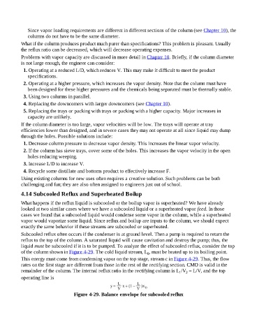
Subcooled reflux often occurs if the condenser is at ground level. Then a pump is required to return the
reflux to the top of the column. A saturated liquid will cause cavitation and destroy the pump; thus, the
liquid must be subcooled if it is to be pumped. To analyze the effect of subcooled reflux, consider the top
of the column shown in Figure 4-29. The cold liquid stream, L , must be heated up to its boiling point.
0
This energy must come from condensing vapor on the top stage, stream c in Figure 4-29. Thus, the flow
rates on the first stage are different from those in the rest of the rectifying section. CMO is valid in the
remainder of the column. The internal reflux ratio in the rectifying column is L /V = L/V, and the top
1
2
operating line is
Figure 4-29. Balance envelope for subcooled reflux